NOTE: DIAGRAMS & ILLUSTRATIONS NOT TO SCALE.
8
Figure 9
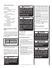
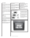
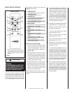
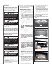
MAINTENANCE
This appliance has been designed to provide
many years of trouble-free service. The com-
ponents that will need to be serviced have been
kept to a minimum. Periodic dusting of the
fi replace is all that should be required.
HEATER/BLOWER REPLACEMENT PROCE-
DURE
1. Turn off power to the fi replace.
2. Let the fi replace completely cool, if it has
been operating.
3. Open the steel curtains (remove glass panel
enclosure, if applicable).
Blower / Heater
Figure 11
Figure 10
Figure 8
4. OPTIONAL: To ensure that the brick panel
isn't accidentally scratched, you may wish
to remove it before proceeding:
Brick Panel Removal Procedure:
a. Remove the 2 screws on the front of the
grate. Remove Grate (see Figure 8).
b. Lift out Log / Ember assembly and set
aside. Caution: Be careful not to scratch
the fi nish.
c. Remove the top brick panel retaining
bracket (see Figure 15). Be very careful
to hold the bracket when removing the
2 screws to ensure the bracket doesn't
fall.
d. Remove the left and right side brick panel
retaining brackets (see Figure 15). Be
very careful to hold the bracket when
removing. Remove the bottom screw fi rst
to avoid the frame falling down after both
screws are removed.
TAKE CARE TO HOLD BRICK PANEL
IN PLACE TO PREVENT POSSIBLE
DAMAGE.
Suggestion: Slide the screens toward the
middle of the fi replace for easier access
to the screws on the sides. Return the
screens to the sides before proceeding
to instruction f.
e. Tip brick panel forward from the top,
just enough to clear screens. Carefully
remove brick panel from fi rebox and set
aside in a safe place.
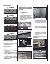
5. Remove the screws which secure the heater
blower mounting plate using a phillips screw-
driver as follows (see Figures 9 & 10):
a. While using one hand to hold the handle
of the heater/blower assembly (see Figure
9), remove the 5 screws which secure
the mounting plate. Remove the 4 side
screws fi rst (2 on each side). Remove
the middle screw that is on the top of
the handle last.
b. Slowly lower the heater/blower assembly
and let it rest on the 2 support chains (1
on each side).
IMPORTANT NOTE: Label all wire loca-
tions prior to disconnecting to ensure
that wires are reconnected in the correct
positions.
6. Replace the heater/blower as follows:
a. Replace the old heater/blower with the
new one. Note: when replacing the
heater/blower, ensure that all the wires
on the heater are correct, otherwise the
heater will not function properly.
b. Turn the power and heater switches on
and check for proper operation.
c. Turn off power to the fi replace.
d. Using one hand to hold the handle of the
heater/blower assembly, slowly push it
back up and line up the holes for the 5
screws. Install the 5 screws to secure
the new heater/blower assembly to the
mounting plate.
7. (If brick panel was removed) Reverse
instructions on Step 4.
8. Reinstall glass panel enclosure, if appli-
cable.
Handle
Heater/blower Mounting Plate
Brick Panel
Remove screws indicated by arrows
Heater/blower Mounting Plate
Be careful not to
damage brick panel
Grate
WARNING
An authorized service represen-
tative should perform any other
servicing.
CAUTION
Handle glass very carefully to
prevent accidental breakage.
CAUTION
Do not use abrasive cleaners on
the glass panel. Do not spray
liquids directly onto any surface
of the fi replace.
CAUTION
Disconnect power before attempt-
ing any maintenance or cleaning
to reduce the risk of fi re, electri-
cal shock or personal injury.
WARNING
When cleaning the fi replace, the
fi replace must be cool.
CLEANING THE GLASS ENCLOSURE PANEL
(OPTIONAL KIT)
Over time the front glass panel may become
dirty or dusty. Dust can be removed by lightly
rubbing the glass surface with a clean, lint free
cloth or paper towel. To remove fi ngerprints
or other marks, use a damp cloth with a good
quality household glass cleaner. The front glass
panel should be completely dried with a clean,
lint free cloth or paper towel.


