


NOTE: DIAGRAMS & ILLUSTRATIONS NOT TO SCALE.
6
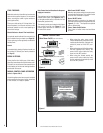
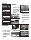
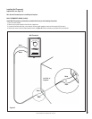
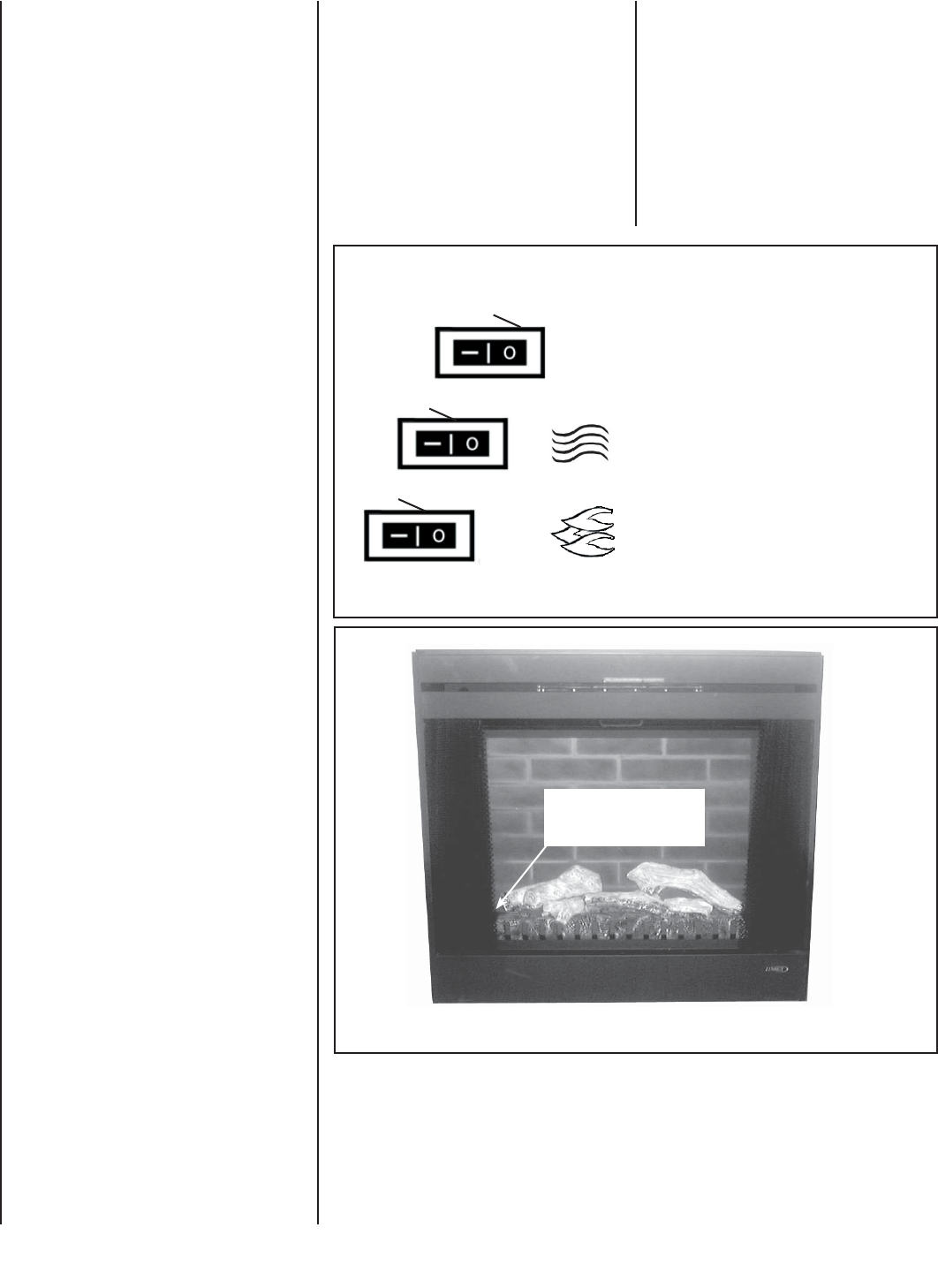
MANUAL CONTROL PANEL
Main Power On/Off (rear most switch)
Figure 4
FINAL FINISHING
Materials such as brick and tile can be extended
down to the top of the fi replace. Do not extend
down, covering the outlet or glass enclosure
panel (optional kit).
There are a wide variety of “fi nished looks” for
these fi replaces, from formal wall decor with
elaborate mantels to rustic wood paneling or
warm brick facings.
Mantel Cabinet or Accent Trim Installations
An optional mantel cabinet kit or an accent trim
kit is available from your dealer (see Page 18).
These options give the appliance an attractive
fi nished look.
Hearth
An aesthetically pleasing fi replace hearth can
be installed, if desired (see hearth protection
on Page 5).
BREAK-IN PERIOD:
During the fi rst few initial uses of this heater,
there may be a release of a slight, harmless odor.
This odor is a normal occurrence caused by the
initial heating of the internal heating elements
and should not reoccur.
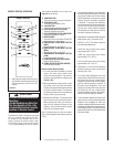
MANUAL CONTROL PANEL OPERATION
(refer to Figures 5 & 6)
Once this appliance has been properly installed
and connected to the power supply as defi ned
in this manual, it is ready to operate.
Flame / Ember On/Off (front most switch)
Figure 5
On
On
On
Off
Off
Off
• When using the main power on/off
switch inside the body, the power on/off
switch outside the body (optional wall
switch kit) must be in the OFF posi-
tion.
• When using power on/off switch outside
the body (optional wall switch), the
power on/off switch inside the body
must be in the OFF position.
• When using the remote control, the
power on/off switch inside the body
and the wall switch (optional kit) must
be on the OFF position.
Heater On/Off (center switch)
Manual Control Switches
are located behind pull
screen on inside fl oor
Note: Ensure the circuit breakers for the power
supply are turned on.
This appliance can be operated either from the
manual control panel (see Figures 4 & 5) or
by using the remote control, wall switch or wall
thermostat (optional kits).
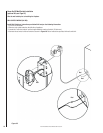
The manual controls are located on the fi rebox
fl oor on the front left (see Figure 5). If an
optional glass enclosure is installed, it must
be removed to access.
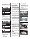
Main Power ON/OFF Switch
When the main power switch is turned on, power
is supplied to the fi replace. This switch must be
on for all other switches to operate.
Heater ON/OFF Switch
When this switch is turned on, the heater will
emit heat in the temperature range selected (see
Figure 6; G, H & I). The fi replace can operate
with or without heat.
Flame / Ember On/Off Switch:
Turns lights on inside ember bed and fl ame
cylinder.