


GAS APPLIANCE INSTALLATION
25
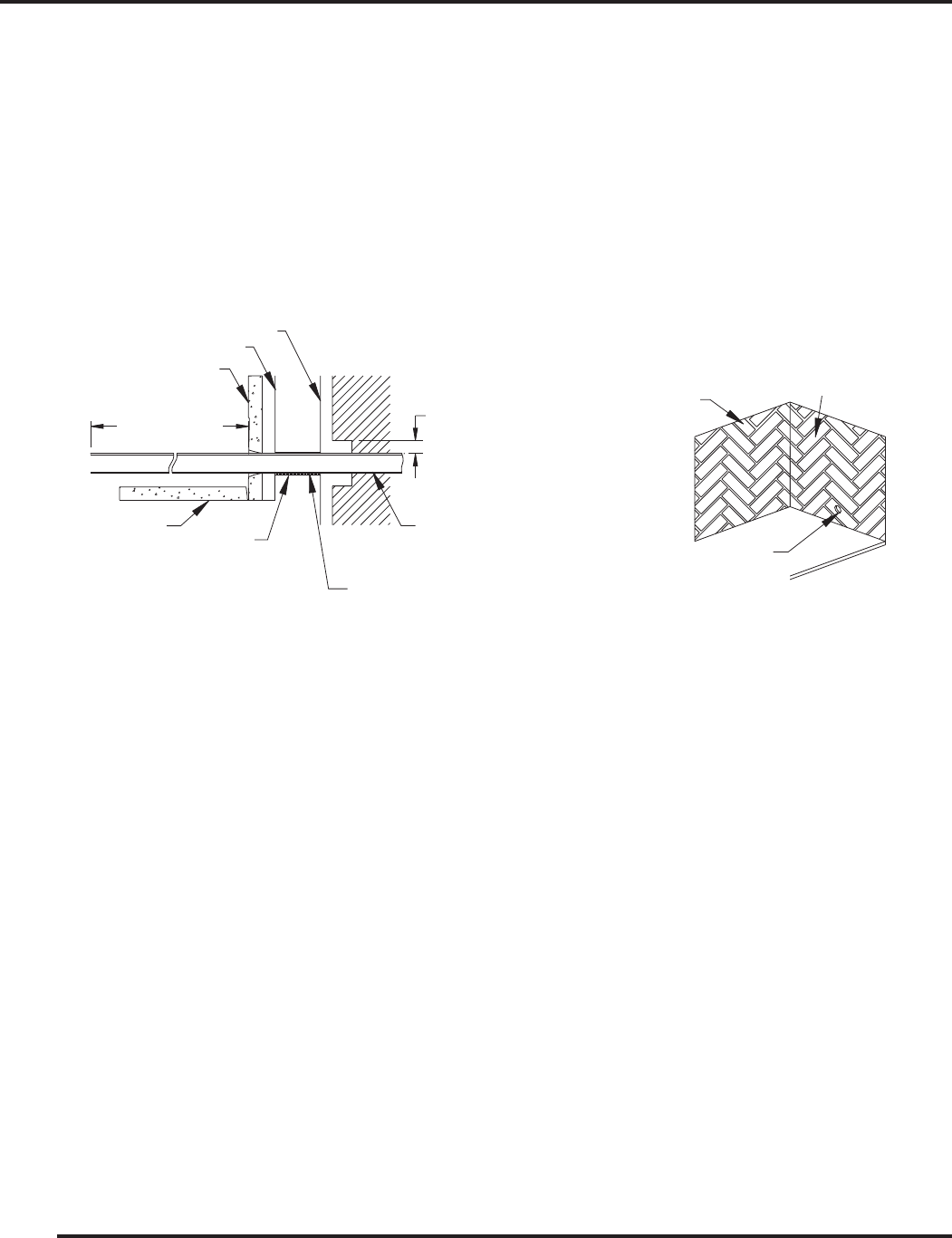
7. Pack the insulation removed in step 4 around the pipe to prevent air flowing through the tube either into or
out of the firebox.
8. Be sure the gas is turned off at the appliance, then turn the gas on at the cut off valve and test the gas line
connections for leaks with soapy water solution or a liquid leak detector. DO NOT USE A MATCH OR
OTHER FLAME SOURCE TO CHECK FOR GAS LEAKS. If a gas leak is detected, turn the gas off
immediately and fix the leak.
9. Proceed with testing the appliance for leaks and adjusting it as required by the manufacturer instructions.
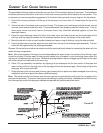
APPLYING DECORATIVE TRIM TO THE FIREPLACE
Do not allow the trim materials to extend closer than 3/8 inch to the vertical edges of the firebox opening if you
plan to equip the fireplace with glass doors.
The face of your fireplace may be left exposed or trimmed with any noncombustible material such as brick,
stone or marble. If a trim is installed, be sure it is fastened snugly to the face of the fireplace. A crack between
the material and the face of the fireplace could pose a fire hazard and impair the proper operation of the
fireplace. Blocking the fireplace with framing and attaching the base to the supporting floor will further reduce
the possibility of such a crack developing.
Wall ties should be fastened to the face of the fireplace with sheet metal screws and placed in the mortar joints
of masonry trim.
Combustible material must not be installed below the top spacers of the fireplace or overlap the sides of the
fireplace face. Seal the face of the fireplace to the surrounding wall with non-combustible caulk or trim materials
to prevent cold air leakage around the fireplace.
The trim should not block or restrict in any way the flow of air into the side air inlets in the face of the fireplace.
Be sure to provide the required floor protection as described in a preceding section of this manual.
Combustible mantles and trim must be installed in accordance with the National Fire Protection Association -
ANSI NFPA 211 Standard - Section 7-2.3.3.
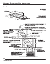
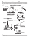
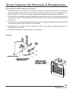
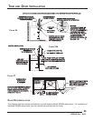
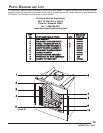
FIGURE 25
53D9028. Rev 1 03/03
GAS LINE PLUMBING DETAIL
GAS LINE PLUMBING DETAIL
CAUTION: WHEN USING A GAS
CAUTION: WHEN USING A GAS
APPLIANCE, THE FIREPLACE DAMPER
APPLIANCE, THE FIREPLACE DAMPER
MUST BE SET IN FULLY OPEN POSITION.
MUST BE SET IN FULLY OPEN POSITION.
REPACK INSULATION AROUND
REPACK INSULATION AROUND
GAS LINE WHERE IT PASSES THRU GAS
GAS LINE WHERE IT PASSES THRU GAS
LINE ACCESS TUBE FOR
LINE ACCESS TUBE FOR
PROPER SEAL.
PROPER SEAL.
GAS LINE ACCESS TUBE
GAS LINE ACCESS TUBE
26" MAX.
26" MAX.
INNER FIREPLACE WRAP
INNER FIREPLACE WRAP
OUTER FIREPLACE WRAP
OUTER FIREPLACE WRAP
SIDE BRICK
SIDE BRICK
FIREPLACE FIREBOX
FIREPLACE FIREBOX
HEARTH BRICK
HEARTH BRICK
COMBUSTIBLE MATERIALS
COMBUSTIBLE MATERIALS
MAY BE LOCATED AT ZERO
MAY BE LOCATED AT ZERO
CLEARANCE TO GAS LINE
CLEARANCE TO GAS LINE
BEYOND 4" FROM FIREPLACE SIDE.
BEYOND 4" FROM FIREPLACE SIDE.
MAINTAIN 1/2" MINIMUM
MAINTAIN 1/2" MINIMUM
AIR SPACE CLEARANCE
AIR SPACE CLEARANCE
TO COMBUSTIBLES FOR
TO COMBUSTIBLES FOR
GAS LINE OUT TO 4" FROM
GAS LINE OUT TO 4" FROM
SIDE OF THE FIREPLACE.
SIDE OF THE FIREPLACE.
SIDE REFRACTORY
SIDE REFRACTORY
BRICK
BRICK
BACK REFRACTORY
BACK REFRACTORY
BRICK
BRICK
KNOCKOUT
KNOCKOUT