Marquis 38 11
VENTING INSTRUCTIONS Cont...
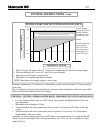
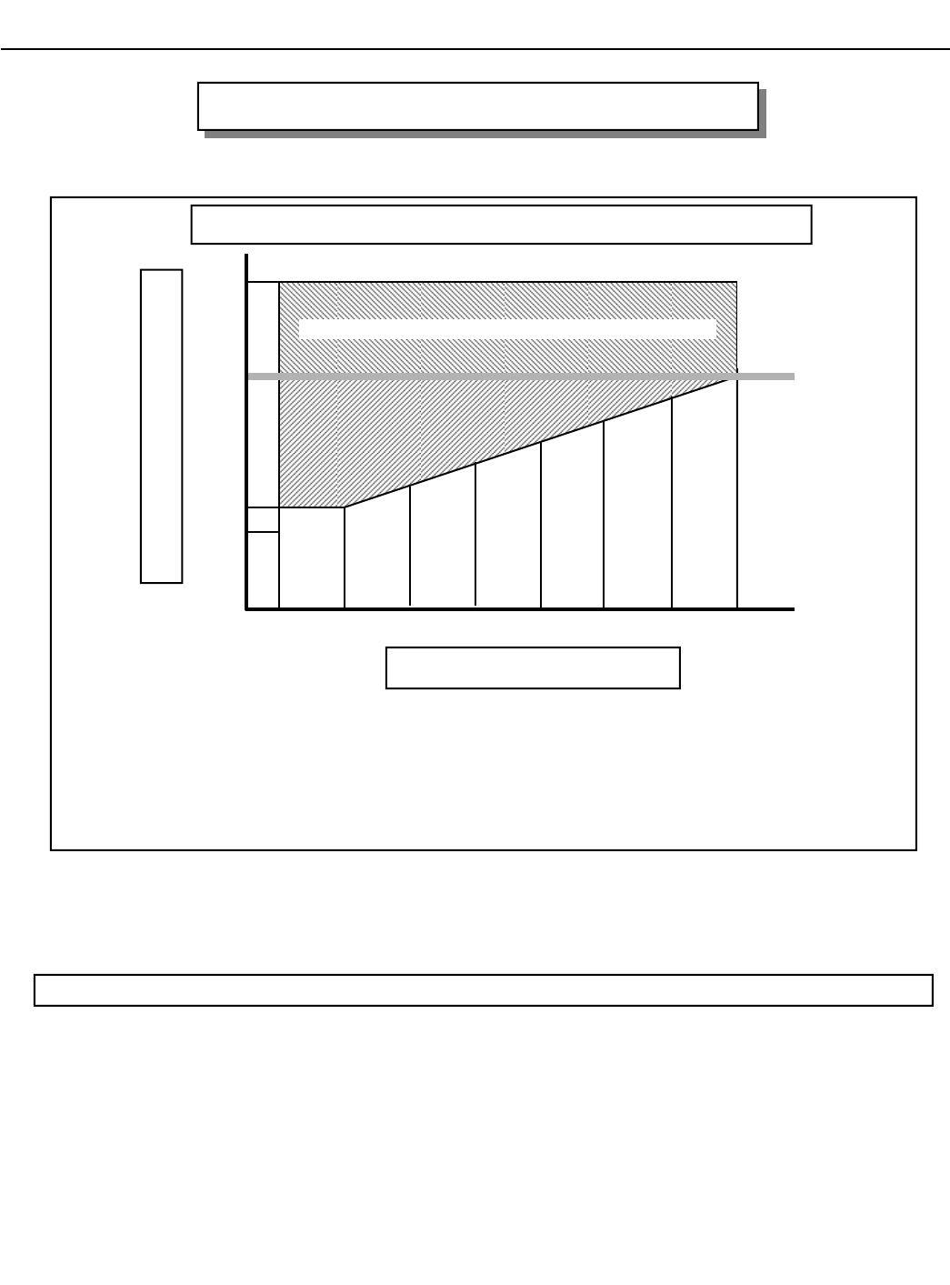
• Chart is for one 90° bend, with 1/4” vertical raise minimum per foot of horizontal length.
• For each additional 90° or two 45°, add 1ft of vertical height.
• Maximum two 90º bends, or equivalent.
• Minimum 2 ft straight length between bends.
Maintain a minimum of 1” clearance to combustibles on sides and bottom and 2” from top surface
of the vent.
The gas fireplace is designed and optimized for majority of the installations with short vents. With
taller vents the flame characteristics will change.
NOTE: Maximum vent lengths subject to local codes.
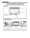
VENTING CHART (FOR TOP VENTED APPLIANCES ONLY)
10 ft
37”
3 ft 1 ft 15 ft
HORIZONTAL LENGTH
(from center of flue outlet to base of termination)
VERTICAL HEIGHT
(from bottom of appliance to center of termination)
7 ft
Venting in this area may require a vent restrictor plate #1.
5 ft 7 ft 9 ft 11 ft 13 ft
31”
Heater
Vertical Venting
between 10 and 24 ft
Rooftop Termina-
tion requires a vent
restrictor plate #2.
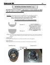
VERTICAL VENTING (THROUGH THE ROOF) FOR ROOFTOP VENTED APPLIANCES
• Use only Simpson Dura-Vent 4 x 6-5/8” direct vent systems and Simpson Dura-Vent vent-
ing components.
• Maximum vertical height of 24 feet.
• Vertical height of the vent system must have at least 3 ft or more per 90
0
elbow in the vent
system.
• Vertical height of the vent system must also be increased 1 ft for every 2 ft of horizontal
length added to the vent system.
Example: A vertical venting system with a 90
0
elbow, a horizontal offset of 4 ft and another 90
0
elbow. Vertical vent height of the vent system must be 3ft + 2ft + 3ft = 8 ft or higher to a maxi-
mum of 24 feet.
Maximum Horizon-
tal run for Rear
Vent is 20” from
back of the unit to
termination or 16”
with a 45
0
elbow.


