


8
UVSRC Vent-Free Fireboxes
20007435
Read all the installation instructions for
the applicable appliance before begin-
ning the installation of the blower.
UVSRC36A Blower Installation
Step 1: Carefully unpack the blower assembly and
familiarize yourself with the parts. Care should be taken
not to damage the fan blades or housing.
Step 2: The SCVS - Variable Speed Control Kit (or
standard wall switch) should be installed before the
blower assembly installation. Please refer to instruc-
tions found in the SCVS Kit.
Step 3: Remove the bottom brick from the fireplace
and carefully place it to the side to prevent damage.
Use a flat blade screwdriver to gently lift up the front
edge of the brick, then pull forward to remove.
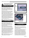
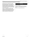
Step 4: Locate the blower access cutout found at the
rear of the hearth pan. Next, remove tape backing from
tape on blower housing. Center the blower assembly in
the access cutout area with the blower outlet duct
pointing upward, then press firmly to attach foam tape
to the back and bottom of the fireplace. (Fig. 9)
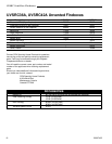
Step 5: Locate the junction box cutout found on the
right side of the hearth pan. Route the powercord under
the hearth pan and plug it into the receptacle outlet
found in the junction box. (Fig. 10)
Step 6: Turn power back on and test blower operation.
Step 7: Replace the bottom brick in the fireplace.
UVSRC42A Installation
Step 1: Carefully unpack the blower assembly and
familiarize yourself with the parts. Care should be taken
not to damage the fan blades or housing.
Step 2: The SCVS - Variable Speed Control Kit (or
standard wall switch) should be installed before the
blower assembly installation. Please refer to instruc-
tions found in the SCVS Kit.
Step 3: Remove the metal hearth cover and the
bottom two right brick panels from the fireplace and
carefully place them to the side to prevent damage.
Step 4: Locate the blower access cutout found at the
rear of the hearth pan. Next, remove tape backing from
tape on blower housing. Center the blower assembly in
the access cutout area with the blower outlet duct
pointing upward, then press firmly to attach foam tape
to the back and bottom of the fireplace. (Fig. 9)
Step 5: Locate the junction box cutout found on the
right side of the hearth pan. Route the powercord under
the hearth pan and plug it into the receptacle outlet
found in the junction box. (Fig. 10)
Step 6: Turn power back on and test blower operation.
Step 7: Replace the metal hearth cover and the
bottom two right panels in the fireplace.
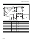
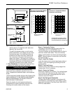
Back Firebrick
Blower
Access
Cutout in
Hearth Pan
Fig. 9 Blower access.
NOTE: Hearth brick and/or hearth cover is removed
as shown to gain access for blower and junction box
installation.
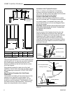
T230
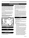
Receptacle
Outlet in
Junction
Box
Junction Box Cutout in
Hearth Pan of Firebox
T231
Fig. 10 Route powercord under the hearth pan and plug into
the receptacle outlet.
Finishing the Fireplace
There are a wide variety of finishing materials available
for your fireplace from formal wall treatments with
marble and mantels to rustic wood paneling, stone or
brick.
IT IS IMPORTANT THAT THE BLACK FACE OF THE
FIREPLACE NOT BE COVERED WITH ANY TYPE OF
COMBUSTIBLE MATERIAL.
Noncombustible facing materials such as marble, brick
or ceramic tile may overlap the black face of the
fireplace up to the opening on either side of the fire-
place. Seal all joints between the black fireplace face
and the wall covering with a heat-resistant material
such as rock wool insulation or mortar. Be sure to use
high temperature adhesive or mortar when anchoring
brick, stone or tile to the face of the fireplace. Check to
see whether man-made brick and stone are made of
noncombustible materials before using them on the
face of the fireplace. Some of these products contain