


5
UVSRC Vent-Free Fireboxes
20007435
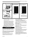
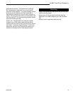
opening and a 10” projection at 24” above the
opening. (Fig. 3b and 3c)
To install the optional canopy, you will need a
phillips screwdriver. The canopy has four holes
along the top edge. The middle two holes are
smaller than the outer two holes. Remove the
four (4) screws in the upper channel (to front
edge) of the firebox. The canopy will fit tightly in
the top front edge of the fireplace opening. Attach
the canopy with the four (4) sheet metal screws
previously removed from the upper channel.
4. Floor Clearances: No clearance is required if the
appliance is installed per these instructions.
Installing the Firebox
This list of specific instructions will help you make
certain that every installation operation is done cor-
rectly. Complete the installation steps in the sequence
shown.
LOCAL BUILDING CODES SHOULD BE CONSULTED
IN ALL CASES AS TO THE PARTICULAR REQUIRE-
MENTS CONCERNING THE INSTALLATION OF
FACTORY BUILT FIREPLACES.
Select the location for the fireplace by taking into
consideration the factors previously outlined in the
Choosing the Location section of the manual.
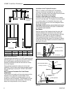
Step 1: Framing the Firebox
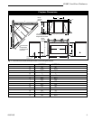
The width of the framed opening must be 39¹⁄₄" for
UVSRC36A or 45¹⁄₄" for UVSRC42A. (Fig. 4)
The entire fireplace can be elevated above the floor to
achieve a raised hearth effect. This can be done by
adding a small platform to achieve the desired height.
NOTE: See pre-wiring of Junction Box and Electrical
Services on Page 7.
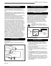
Step 2: Install the Firebox
Install the firebox into the framed opening by setting it
directly in front of the opening and sliding it into the
proper position.
Step 3: Level the Firebox
Check the level of the firebox on the top edge of the
fireplace face. Shim if necessary.
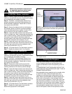
Step 4: Secure the Firebox
Secure the fireplace to the framing. The nailing flanges
on the firebox will make securing the firebox to the
frame quick and easy. Use appropriate size nails or
screws to secure the firebox.
Step 5: Gas Piping and Connection
The gas piping must be installed in accordance with
local codes or, in the absence of local codes, in accor-
dance with the National Fuel Gas Code, ANSI Z223.1/
NFPA 54, latest edition.
8
10
12
14
16
18
20
22
24
24
68
10
8
10
12
14
16
18
20
22
24
68
10
6
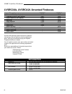
42"
5" Min.
9¹⁄₂"
Min.
24"
Min.
10"
6"
16"
Min.
Combustible
Perpendicular Wall
3a
Noncombustible
Material
Fireplace
Opening
FP604a
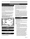
Clearances
without Canopy
3b
3c
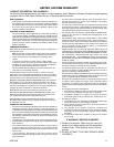
Clearance* from Top of Fireplace Opening (“)
Mantel (Combustible)
Projections (“)
Clearance to Combustible Mantel
Projections without Canopy
T225
Fig. 3 Clearances to combustibles.
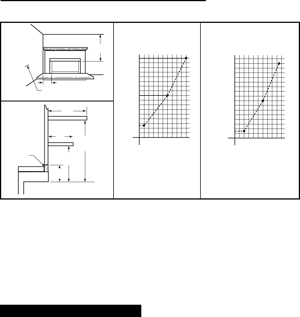
*Combustible projections above
the fireplace must be within the
area described by the dashed line.
Clearance* from Top of Fireplace Opening (“)
Mantel (Combustible)
Projections (“)
3d
Clearance to Combustible Mantel
Projections with Canopy