


7
UVSRC Vent-Free Fireboxes
20007435
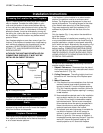
Finishing the Fireplace
There are a wide variety of finishing materials available
for your fireplace from formal wall treatments with
marble and mantels to rustic wood paneling, stone or
brick.
IT IS IMPORTANT THAT THE BLACK FACE OF THE
FIREPLACE NOT BE COVERED WITH ANY TYPE OF
COMBUSTIBLE MATERIAL.
Noncombustible facing materials such as marble, brick
or ceramic tile may overlap the black face of the
fireplace up to the opening on either side of the fire-
place. Seal all joints between the black fireplace face
and the wall covering with a heat-resistant material
such as rock wool insulation or mortar. Be sure to use
high temperature adhesive or mortar when anchoring
brick, stone or tile to the face of the fireplace. Check to
see whether man-made brick and stone are made of
noncombustible materials before using them on the
face of the fireplace. Some of these products contain
combustible materials. Combustible wall coverings such
as paneling or wallboard may not overlap the black face
of the fireplace. The space between the wall covering
and the fireplace should be sealed with a heat-resistant
material such as rock wool insulation or mortar.
NOTE: An "L" shaped steel lintel must be installed
across the top of the firebox opening where facing
materials such as brick or stone are used on the face of
the firebox. It acts as a support/firestop. It should be
attached to the face of the fireplace with screws and
sealed to the fireplace with a heat-resistant sealer.
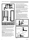
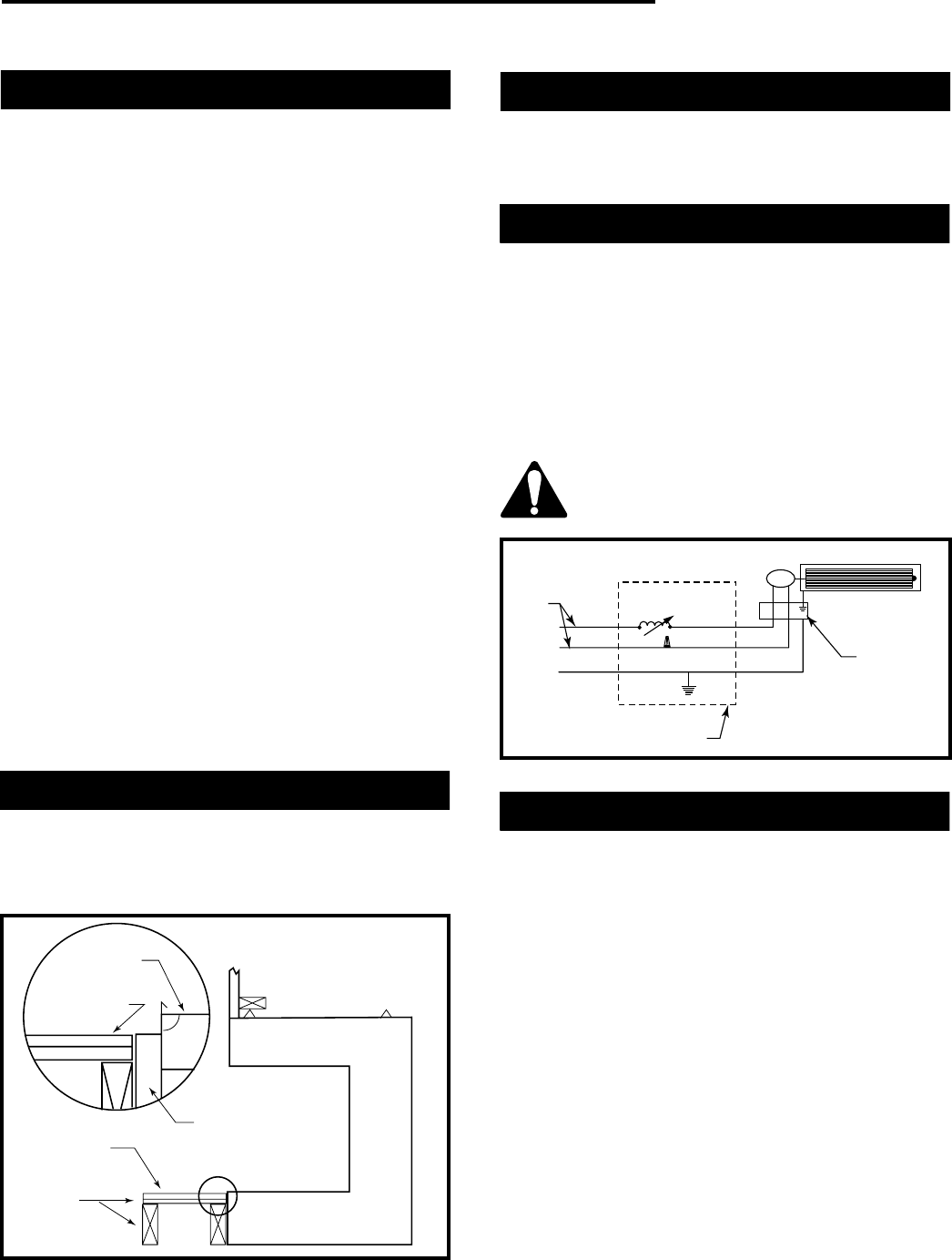
Hearth Extension
A hearth extension may be used but is not required for
these fireboxes.
A raised hearth extension may be used as shown in
Figure 7.
Hearth
Brick
Hearth
Extension
Surround
Combustibles
Allowed (No
Carpet or Vinyl)
Combustible
Platform
T228
Fig. 7 Raised hearth extension.
Pre-Wiring of Junction Box
Wiring should be connected at the junction box located
on the right side of the firebox prior to the installation of
the blower kit. A standard wall box should be used to
contain the SCVS - Variable Speed Control Kit.
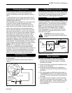
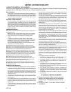
Electrical Services
If an electrical supply of 120V is being roughed in to the
fireplace junction box to provide for future installation of
optional blower kit, the wiring should be connected to
the junction box located on the right side of the firebox.
NOTE: All electric connections are to be made in
accordance with CSA Standard C22.1-Canadian
Electrical Code part 1 or with the National Electrical
Code, ANSI/NFPA 70 (latest edition) and/or in accor-
dance with local codes.
CAUTION: Should this blower require
servicing, the power supply must be discon-
nected.
M
Black
White
G
Wall Electrical Box
Firebox
Accessory
Junction
Box
120
Volt
Speed Control
Switch
T229
Fig. 8 Blower wiring diagram.
Fan
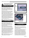
Blower Installation
BEFORE YOU BEGIN...A FEW BASIC RULES
1. Check to ensure that electrical service has been
provided to the junction box located in the bottom
chamber of the firebox.
2. Check local building codes before installation of the
firebox and the blower kit.
3. All wiring must be installed and/or inspected as
necessary to comply with the local authority having
jurisdiction.
4. The circuit breaker controlling the power supply to
the pre-wired junction box in the appliance must be
in the “OFF” position before beginning installation of
the blower.
5. The appliance, when installed, must be electrically
grounded in accordance with local codes or - in the
absence of local codes - with the National Electrical
Code, ANSI/NFPA 70 or the Canadian Electrical
Code, CSA C22.1.