20 Fireplace Insert Installation (for qualified installers only)
© Travis Industries 100-01166 4040907
Zero-Clearance (Metal) Fireplace Requirements
• Must utilize a positive (full reline) or direct connection (block-off plate)
• Must be manufactured by one of the following manufacturers:
• Marco • Majestic • Heatilator • Preway • Tempco • Superior
• Entire fireplace, including chimney, must be clean and undamaged. Any damage must be repaired
prior to installation of the insert
• Entire fireplace, including chimney, must meet local building requirements
• Chimney height: 15' minimum; 33' maximum. Minimum cross section: 28.65 square inches
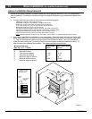
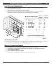
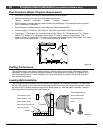
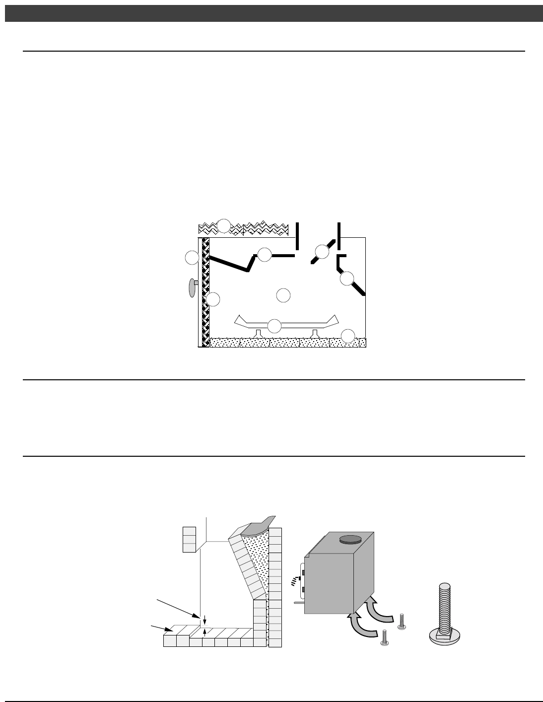
• The damper ("A") and grate ("B") must be removed (see Figure 18). The smoke shelf ("C"), internal
baffles ("D"), screen ("E"), and metal or glass doors ("F") may be removed (if applicable). The
masonry lining ("G"), insulation ("H"), and any structured rigid frame members (metal sides, floor, door
frame, face of the fireplace, etc. – "I") may not be removed or altered
C
B
F
I
D
E
A
G
H
Figure 18
Drafting Performance
This appliance relies upon natural draft to operate. External forces, such as wind, barometric pressure,
topography, or factors of the home (negative pressure from exhaust fans, chimneys, air infiltration, etc.),
may adversely affect draft. Travis Industries can not be responsible for external forces leading to less
than optimal performance.
Leveling Bolt Installation
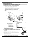
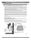
Two leveling bolts are included to level the insert if the fireplace has a stepped-up hearth. To install, raise
the rear of the insert up and insert the leveling bolts into the holes in the rear corners of the insert. Adjust
the bolts until they extend the same height as the hearth steps up. After the insert is installed, fine-tune
the leveling bolts to level the insert (see Figure 19).
This distance is the
hearth step-up. The
leveling bolts should
stick out this far from the
base of the insert.
Fireplace
Hearth
The leveling bolts go
into the holes at the
rear corners of the
insert.
Figure 19


