


60
8 Maintenance
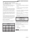
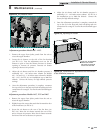
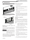
TRANSITION BOX SCREWS
Figure 8-5_Loosening the transition box screws,
Models 1437, 1797 and 2067 only
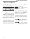
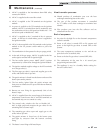
INCREASE AIR
PRESSURE
DECREASE
A
IR PRESSURE
Figure 8-6_Adjusting the air shutter
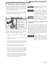
Servicing a hot surface igniter and
ignition module
This unit uses a proven hot surface ignition module and a
hot surface igniter. The hot surface ignition module is not
repairable. Any modification or repairs will invalidate the
warranty.
Do not attempt to repair a faulty hot
surface igniter or ignition module. Any
modification or repairs may create
hazardous conditions that result in
property damage, personal injury, fire,
explosion and/or toxic gases.
ƽ WARNING
A faulty hot surface igniter or ignition module must be
replaced with an identical part. A specification igniter
and ignition module for this specific unit is available from
your local distributor. Do not use general purpose field
replacement ignition modules or igniters.
Sequence of operation
Overview
This sequence of operation can be considered the order of
events in sequential order that occur after the appliance has
received a call for heat. The process begins with 120VAC
power entering the appliance and ends with the appliance
going into an idle state after completion of a successful call
for heat.
Ignition system checkout
1. Turn off gas supply to unit.
2. Turn electric power on.
3. Adjust the set point on the temperature control to a
setting above water temperature or to the highest safe
setting.
4. The igniter will cycle on trial for ignition.
5. The ignition module will lock out and turn the alarm
light on.
6. Adjust the Set Point Differential and High-Fire Offset to
the desired settings.
7. Turn on gas supply.
8. Press the module reset button to reset the ignition
module. This is a red button beside the ignition module
or on the diagnostic panel on the header-end of the unit.
9. If ignition system fails to operate properly, repair work
must be performed by a qualified service person or
installer.
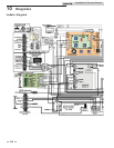
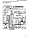
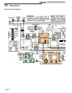
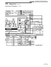
Note: The following descriptions do not include
remotely connected devices that may be
connected to the appliance. Refer to the wiring
diagram for actual point to point wiring
connections that show power delivery.
Installation & Service Manual
1. The POWER switch is placed in the “ON” position.
2. 120VAC power is supplied to the control transformer along
with L1 and F1 on the ignition module.
3. 24VAC is supplied to the electronic temperature control,
the ignition module and the adjustable high limit control.
4. 24VAC is then supplied to the auxiliary limit control
(if equipped).
5. If equipped, 24VAC is supplied to a low water cut-off and
then to the high and low gas pressure switches.
6. 24VAC is supplied to the continuous alarm terminals A1
and A2 and then to the remote stage one terminal strip,
1C and 1NO.
7. 24VAC is supplied to the electronic temperature control.
8. The electronic temperature control then calls for heat.