


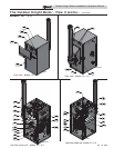
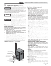

The Outdoor Knight Boiler - How it works...
1. Stainless steel heat exchanger
Allows system water to flow through specially designed
coils for maximum heat transfer, while providing
protection against flue gas corrosion. The coils are
encased in a jacket that contains the combustion process.
2. Combustion chamber access cover
Allows access to the combustion side of the heat
exchanger coils.
3. Blower
The blower pulls in air and gas through the venturi (item
5). Air and gas mix inside the blower and are pushed into the
burner, where they burn inside the combustion chamber.
4. Gas valve
The gas valve senses the negative pressure created by the
blower, allowing gas to flow only if the gas valve is
powered and combustion air is flowing.
5. Venturi
The venturi controls air and gas flow into the burner.
6. Flue gas sensor (limit rated)
This sensor monitors the flue gas exit temperature. The control
module will modulate and shut down the boiler if flue gas
temperature gets too hot. This protects the flue pipe from
overheating.
7. Boiler outlet temperature sensor (housed with the
high limit sensor)
This sensor monitors boiler outlet water temperature (system
supply). If selected as the controlling sensor, the control
module adjusts boiler firing rate so the outlet temperature is
correct.
8. Boiler inlet temperature sensor
This sensor monitors return water temperature (system
return). If selected as the controlling sensor, the control
module adjusts the boiler firing rate so the inlet temperature is
correct.
9. Temperature and pressure gauge (field installed, not
shown)
Monitors the outlet temperature of the boiler as well as the
system water pressure.
10. Electronic LCD display
The electronic display consists of 4 buttons, a navigation dial
and a multiple line liquid crystal display.
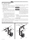
11. Flue pipe adapter
Allows for the connection of the vent system to the
boiler.
12. Burner (not shown)
Made with metal fiber and stainless steel construction,
the burner uses pre-mixed air and gas and provides a
wide range of firing rates.
13. Water outlet (system supply)
NPT water connection that supplies hot water to the
system, either 1" or 1-1/4", depending on the
model.
14. Water inlet (system return)
NPT water connection that returns water from the
system to the heat exchanger, either 1" or 1-1/4",
depending on the model.
15. Gas connection pipe
Threaded pipe connection, either 1/2" or 3/4",
depending on the model. This pipe should be connected
to the incoming gas supply for the purpose of delivering
gas to the boiler.
16. SMART SYSTEM Control Module
The SMART SYSTEM Control responds to internal and
external signals and controls the blower, gas valve, and pumps
to meet the heating demand.
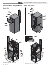
17. Manual air vent
Designed to remove trapped air from the heat exchanger
coils.
18. High voltage junction box
The junction box contains the connection points for the line
voltage power and all pumps.
19. Boiler drain port
Location from which the heat exchanger can be drained.
20. Low voltage connection board
The connection board is used to connect external low voltage
devices.
21. Low voltage wiring connections
Conduit connection points for the low voltage
connection board.
22. Condensate drain connection
Connects the condensate drain line to a 1/2" PVC union.
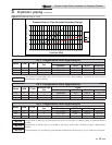
23. Access cover - top front
Provides protection of the control panel / display from outside
elements.
24. Access cover - bottom front
Provides access to the burner.
25. Ignition electrode
Provides direct spark for igniting the burner.
26. Flame inspection window
The quartz glass window provides a view of the burner
surface and flame.
27. Relief valve
Protects the heat exchanger from an over pressure condition.
The relief valve provided with the unit is set at 30 psi.
28. Flame sensor
Used by the control module to detect the presence of burner
flame.
29. Line voltage wiring connections
Conduit connection points for the high voltage junction box.
30. Top access cover
Provides access to the internal components.
31. Power switch
Turns 120 VAC ON/OFF to the boiler.
32. Leveling legs
Used to allow the heat exchanger to be leveled. This is needed
for the proper draining of the condensate from the combustion
chamber.
33. Air pressure switch
The air pressure switch detects blocked inlet conditions.
34. Transformer
The transformer provides 24V power to the integrated control.
35. High limit sensor (housed with the outlet
temperature sensor)
Device that monitors the outlet water temperature. If the
temperature exceeds its setting, the integrated control will
break the control circuit, shutting the boiler down.
36. Gas shutoff switch
An electrical switch designed to cut power to the gas valve to
prevent releasing any gas.
37. Over-temp switch (Model 286 Only) (located underneath
access cover)
An electrical switch designed to shut down boiler operation in
the event the outer back of the heat exchanger, directly above the
flue connection exceeds 604°F (318°C). This is a one time
switch and could warrant a heat exchanger replacement. Check
the integrity of the rear refractory at the back of the upper coil if
the switch opens.
38. Air cover
Covers the over-temp switch and the flue collar with flue sensor.
39. Flue pipe assembly
Factory supplied components for a complete venting system.
4
Outdoor Knight Boiler Installation & Operation Manual