


5 Field wiring
ELECTRICAL SHOCK HAZARD – For
your safety, turn off electrical power supply
before making any electrical connections
to avoid possible electric shock hazard.
Failure to do so can cause severe personal
injury or death.
Wiring must be N.E.C. Class 1.
If original wiring as supplied with boiler
must be replaced, use only type 105°C wire
or equivalent.
Boiler must be electrically grounded as
required by National Electrical Code ANSI/
NFPA 70 – latest edition.
All wiring exterior to the appliance must be
enclosed in approved conduit.
Installation must comply with:
1. National Electrical Code and any other national, state,
provincial, or local codes, or regulations.
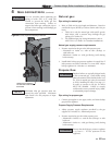
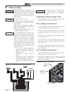
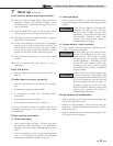
Line voltage connections
1. Connect 120 vac power wiring to the line voltage terminal
strip in the junction box, as shown in FIG. 5-1.
2. Provide and install a fused disconnect or service switch
(15 amp recommended) as required by the code (see
FIG. 5-1).
3. The boiler pump is shipped loose. Wire the boiler pump
as shown in FIG. 5-1.
4. When connecting a domestic hot water (DHW) pump,
connect the wiring to the line voltage terminal strip as
shown in FIG. 5-1.
5. To activate a system pump, wire as shown in FIG. 5-1.
If the motor is larger than 1/8 hp or 1.8 amps, you must
isolate with a relay.
Figure 5-1 Line Voltage Field Wiring Connections
Label all wires prior to disconnection
when servicing controls. Wiring errors
can cause improper and dangerous
operation.
ƽ WARNING
NOTICE
ƽ CAUTION
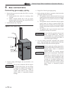
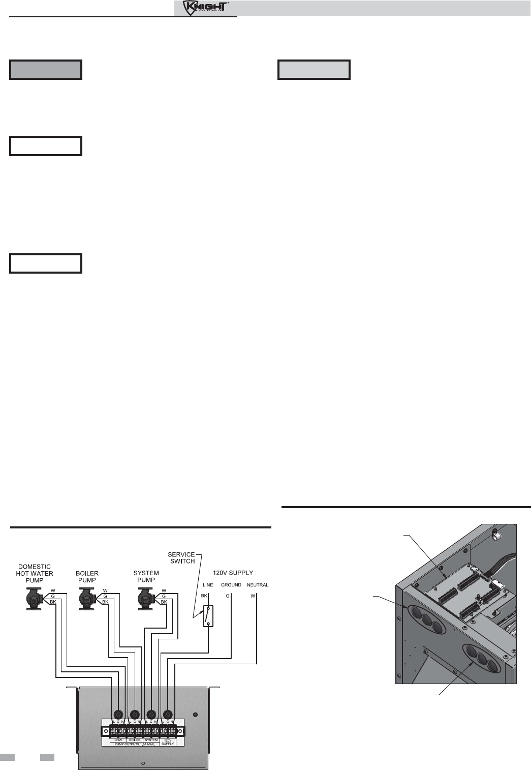
Low voltage connections
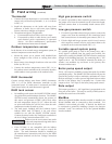
1. Route all low voltage wires through the knockouts in the
rear of the boiler, as shown in FIG. 5-2.
2. Connect low voltage wiring to low voltage connection
board as shown in FIG. 5-3 on page 31 of this manual and
the boiler wiring diagram.
IMG00386
LOW VOLTAGE
CONNECTION
BOARD
LOW VOLTAGE
WIRING
KNOCKOUTS
LINE VOLTAGE
WIRING KNOCKOUTS
Figure 5-2 Routing Field Wiring
In accordance with Section 303 of the 2007
Energy Act, this boiler is equipped with a
feature that saves energy by reducing the
boiler water temperature as the heating
load decreases. This feature is equipped
with an override, which is provided
primarily to permit the use of an external
energy management system that serves the
same function. This override MUST NOT
be used unless at least one of the following
conditions is true:
1. An external energy management
system is installed that reduces the
boiler water temperature as the heating
load decreases.
2. This boiler is not used for any space
heating.
3. This boiler is part of a modular or
multiple boiler system having a total
input of 300,000 Btu/hr or greater.
4. This boiler is equipped with a tankless
coil.
NOTICE
28
Outdoor Knight Boiler Installation & Operation Manual