


Installation & Operation Manual
36
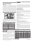
6 System piping
System water piping methods
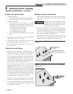
Observe a minimum of 1 inch clearance around all un-insulated
hot water pipes when openings around the pipes are not
protected by non-combustible materials.
General piping information
Basic steps are listed below along with illustrations on the
following pages (FIG.’s 6-4 thru 6-8), which will guide you
through the installation of the Armor water heater.
1. Connect the cold water supply to the inlet side of the water
heater, make sure to install with pipe sealant compound.
2. Connect the hot water supply to the outlet side of the water
heater, make sure to install with pipe sealant compound.
3. Install a backflow preventer on the cold feed make-up water
line.
4. Install the factory supplied pump as shown in FIG.’s 6-4
thru 6-8.
5. Install an expansion tank on the system supply. Consult the
tank manufacturer’s instruction for specific information
relating to tank installation. Size the expansion tank for the
required system volume and capacity.
6. Install a drain valve at the lowest point of the system.
7. This appliance is supplied with a relief valve sized in
accordance with ASME Boiler and Pressure Vessel Code,
Section IV (“Heating Boilers”). Pipe the discharge of the
safety relief valve to a suitable drain to prevent injury in the
event of pressure relief. Pipe the discharge to a drain.
Provide piping that is the same size as the safety relief valve
outlet. Never block the outlet of the safety relief valve.
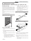
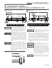
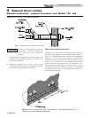
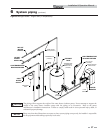
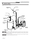
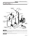
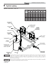
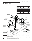
See the *piping illustrations included in this section,
FIG.’s 6-4 thru 6-8 for suggested guidelines in piping the Armor
water heater.
*Please note that these illustrations are meant
to show system piping concept only, the
installer is responsible for all equipment and
detailing required by local codes.
NOTICE
MODEL PADDLE SIZE
SENSITIVITY SCREW
ADJUSTMENT
Note: Paddles are included with the flow switch.
150 #1 9 turns
199 #1 6 turns
285 #3 8¾ turns
399 #1 8 turns
500 #1 7½ turns
600 #1 7 turns
700 #1 6½ turns
800 #1 5½ turns
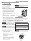
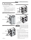
RELIEF VALVE
FLOW SWITCH
PADDLE
TEE WITH 1” FITTING ON TOP
CLOSE NIPPLE
TEE WITH 3/4” FITTING ON TOP
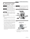
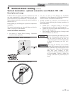
6. Install the assembled flow switch into the 1 inch fitting of
the tee installed in Step 4 (see FIG. 6-1).
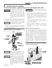
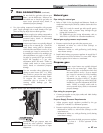
Flow switch adjustment
Refer to Table 6A for the proper setting of the sensitivity screw.
For reference, the position of the screw prior to setting should be
turned clockwise with a Phillips driver until it stops (FIG. 6-2).
Proceed to turn the screw counterclockwise the amount of turns
listed in Table 6A based on the model.
Consult the manufacturer’s instructions for wiring the flow
switch to your system.
NOTICE
Be sure to install flow switch so that the arrow
on the flow switch is pointing in the direction
of the flow (see FIG. 6-2).
Table 6A Paddle Size / Sensitivity Screw Adjustment
Figure 6-1 Flow Switch and Relief Valve Installation
NORMALLY
OPEN
SENSITIVITY
ADJUSTMENT
NORMALLY
CLOSED
COMMON
GROUND
NOTICE
Turn the sensitivity screw clockwise to increase
the flow rate required to activate the switch. Turn
the sensitivity screw counterclockwise to decrease
the flow rate required to activate the switch.
Flow switch and relief valve installation
Basic steps are listed below to guide you through the installation
of the flow switch and relief valve provided with the unit.
1. Install the tee with the 3/4 inch fitting positioned vertically
and on the top as shown in FIG. 6-1.
2. Install the relief valve into the 3/4 inch fitting of the tee
installed in Step 1 (FIG. 6-1).
3. Install the close nipple on the downstream side of the
temperature and pressure relief valve tee (FIG. 6-1).
4. Install the tee with the 1 inch fitting positioned vertically
and on the top (FIG. 6-1).
5. Attach the paddle to the flow switch per the manufacturer’s
instructions. Reference Table 6A to select the correct
paddle for the pipe size used (consult the manufacturer’s
instructions for a detailed explanation).
For Example: If using a 1 1/4 inch pipe size (Models
AWN150 - AWN199) select paddle #1.
ƽ WARNING
The relief valve, tee and other necessary
fittings are shipped in the install kit with the
water heater and are to be field installed.
Figure 6-2 Flow Switch Adjustment