


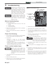

3 Troubleshooting
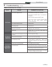
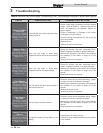
Table 3E Troubleshooting Chart - Fault Messages Displayed on Water Heater Interface
FAULT DESCRIPTION CORRECTIVE ACTION
Flow Switch/
LWCO
(will require a manual
reset once condition has
been corrected. Press
the RESET button on
the display to reset.)
Either the flow switch or the optional AUX
switch is not making.
• Check water heater pump operation on a call for heat.
• Check for closed valves or obstructions in the water
heater piping.
• Verify system is full of water and all air has been
purged from the system.
• Check for loose or misplaced jumpers if flow switch is
not installed.
Blown fuse.
• Replace fuse F2 on the control board, see page 38 of
this manual.
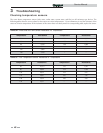
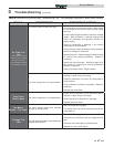
Condensate
Drain Blocked
(will require a manual
reset once condition has
been corrected. Press
the RESET button on
the display to reset.)
The blocked drain switch has detected
excessive condensate build up inside the
unit.
• Check condensate tube from unit to floor drain for
proper installation and obstructions.
• Inspect condensate trap for blockage. Clean if
necessary.
• Check for loose wiring connection at wire harness
plug.
• Bad blocked drain switch. Replace switch.
Flame out of
Sequence
(will require a manual
reset once the condition
has been corrected.
Press the RESET button
on the display to reset.)
The flame detector circuit is seeing a flame
signal while no flame is present.
• Check supply voltage for proper polarity.
• Check external wiring for voltage feedback.
• Check the flame rod and make sure it is clean.
• Check the internal wiring for bad connections.
• Replace main control board.
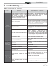
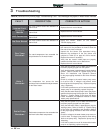
Gas Valve /
Connection
(will require a manual
reset once the condition
has been corrected.
Press the RESET button
on the display to reset.)
The main control board did not detect the
gas valve.
• Check wiring harness connection at the gas valve and
at the main control board.
• Replace the gas valve wire harness.
• Replace the gas valve.
• Replace the main control board.
Burner Did Not
Light
(will require a manual
reset once the condition
has been corrected.
Press the RESET button
on the display to reset.)
The unit has failed to prove main burner
ignition. It will require a manual reset before
attempting to fire again.
• Inspect spark electrode and associated wiring for
damage and connection. Reference page 35 of this
manual for removal and cleaning procedures.
Replace if necessary.
• Check for proper electrical grounding of the unit.
• Check incoming supply gas pressure. Natural gas
pressures should be between 4 - 14 inches w.c.
(1.0 - 3.5 kPa) and LP gas pressures should be
between 8 - 14 inches w.c. (2.0 - 3.2 kPa). Refer
to Section 7 - Gas Connections of the Armor X2
Installation and Operation Manual for detailed
information concerning the gas supply.
• Verify that the tube from the gas valve to the
air inlet is connected and is not damaged.
• Verify that the vent/air intake pipes are correctly
installed and that there are no obstructions.
• Check for 24 VAC to the gas valve at the 2-pin
connection on the side of the main control board
during the ignition attempt. If no voltage is present,
replace the main control board.
Service Manual
42