


3 Troubleshooting
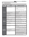
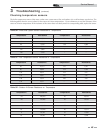
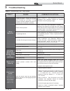
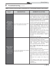
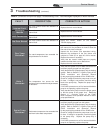
Table 3G Troubleshooting Chart - Combustion Levels
POSSIBLE CAUSE CORRECTIVE ACTION
Vent/Air Intake Length
or Obstruction
• Refer to Section 2 - General Venting of the SYNC Installation and Operation Manual
for the proper venting and air intake methods for the SYNC boiler.
• Check for obstructions at the vent/air intake terminals.
Gas Supply Pressure
• Refer to Section 6 - Gas Connections of the SYNC Installation and Operation
Manual for the proper gas supply for the SYNC boiler.
Dirty/Damaged Burner
• Refer to page 39 of this manual for burner removal and cleaning procedures.
• Replace burner if necessary.
Gas Valve Adjustment
• Refer to page 55 of this manual for the gas valve adjustment procedure.
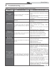
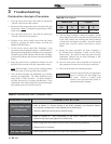
Table 3H Flue Products
Natural Gas Propane
CO
2
O
2
CO
2
O
2
8.0% - 10% 3.0% - 6.5% 9.0% - 11% 4.1% - 6.9%
You must replace the flue gas temperature
sensor to prevent flue gas spillage into
the room. Failure to comply could
result in severe personal injury, death, or
substantial property damage.
ƽ WARNING
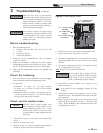
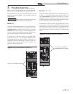
Combustion Analysis Procedure
1. Turn the main power off to the boiler by placing the
“On/Off” switch in the OFF position.
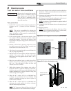
2. Remove the flue temperature sensors from the flue pipe
connections. Note: Combustion measurements will be
made at this point.
3. Turn the main power on to the boiler by placing the
“On/Off” switch in the ON position.
4. Navigate to the Service Mode Screen from the Status
Screen by pressing the MAIN button and then the
SERVICE MODE button.
5. On the Service Screen place Heat Exchanger 1 into
operation by selecting Heat Exchanger 1 with the SELECT
button and turning the heat exchanger on by pressing the
ON/OFF button (OFF indicates that the heat exchanger
is off and ON indicates that the heat exchanger should be
firing).
6. Insert the probe from a combustion analyzer into the
hole left by the removal of the flue temperature sensor.
Note: Heat Exchanger 1 is the top heat exchanger; please
ensure the probe is in the top flue sensor location.
7. Once the heat exchanger has modulated up to full fire
measure the combustion. The values should be in the
range listed in Table 3H above. CO levels should be
less than 200 ppm for a properly installed unit. If the
combustion is not within range reference the chart below
for possible causes and corrective actions.
8. Once the Heat Exchanger 1 analysis is complete, test the
safety shutoff device by turning the manual shutoff valve
to the OFF position and ensuring that Heat Exchanger
1 shuts down and registers an alarm. Open the manual
shutoff valve, reset the control, and return to Service
Mode.
9. Repeat the same procedure for Heat Exchanger 2
by selecting Heat Exchanger 2 while on the Service
Mode Screen. Be certain to insert the probe from the
combustion analyzer into the Heat Exchanger 2 flue
temperature sensor location.
10. Turn the main power off to the boiler and replace the
flue temperature sensor into the flue pipe connection.
11. Place the boiler back into normal operation.
54
Service Manual