


Table 3F (continued from previous page) Troubleshooting Chart - Fault Messages Displayed on Boiler Interface
FAULT DESCRIPTION CORRECTIVE ACTION
Automatic Reset
High Limit / HEX-
Temp SW
(will require a manual
reset once the condition
has been corrected. Press
the RESET button on the
display to reset.)
Either the auto-reset high limit (optional),
or the O-temp heat exchanger switch as
opened.
Automatic Reset High Limit:
• Verify that the system is full of water and that all air
has been properly purged from the system.
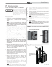
• Verify that the boiler is piped properly into the heating
system. Refer to Section 6 - Hydronic Piping of the
SYNC Installation and Operation Manual
for the proper piping methods for the SYNC.
• Check voltage to boiler pump motor on a call for
heat. If voltage is not present, check wiring back to
the pump relay.
• Replace the pump relay if necessary.
• If 120 VAC is present on a call for heat and the boiler
pump is not operating, replace the pump.
• If the system pump is a variable speed pump, ensure
that the system flow is not less than the boiler flow.
• If operating on either an inlet or system supply
sensor, check temperature setting of the main control
board.
• If the high limit has tripped, check setting of the
device.
• Check resistance of water sensors and compare to
Table 3B on page 45 of this manual. Replace sensor
if necessary.
• Replace high limit.
HEX Temp SW:
• Check continuity across two contacts. Wires should
be connected at both poles of normally closed switch.
• Inspect the rear of the inner combustion chamber
at the burner level, for refractory breakdown/missing.
Replace the refractory if no damage to the heat
exchanger as a result of the burner, otherwise,
replace the heat exchanger.
• Faulty O-temp heat exchanger switch. Replace
switch.
Blower RPM’s
Too Low
(will require a manual
reset once the condition
has been corrected. Press
the RESET button on the
display to reset.)
The actual fan rpm is 30% lower than what
is being called for. Reference the Burners
Screen information on page 32 of this
manual.
• Vent/air intake lengths exceed the maximum allowed
lengths. Refer to Section 2 - General Venting of the
SYNC Installation and Operation Manual for
proper lengths.
• Check for obstruction or blockage in the vent/air
intake pipes or at terminations.
• Check the wiring connections at the fan and at the
main control board.
• Replace the fan.
• Replace the main control board.
Blown fuse.
• Replace fuse F4 on the control board, see page 43 of
this manual.
50
3 Troubleshooting
Service Manual