


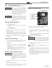

3 Troubleshooting (continued)
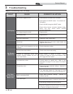
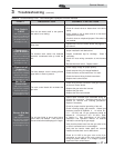
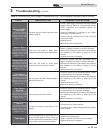
Table 3F Troubleshooting Chart - Fault Messages Displayed on Boiler Interface
FAULT DESCRIPTION CORRECTIVE ACTION
Flow Switch/
LWCO
(will require a manual
reset once condition has
been corrected. Press
the RESET button on
the display to reset.)
Either the low water cutoff or the optional
flow switch is not making.
• Check boiler pump operation on a call for heat.
• Check for closed valves or obstructions in the boiler
piping.
• Verify system is full of water and all air has been
purged from the system.
• Check for loose or misplaced jumpers if flow switch is
not installed.
Blown fuse.
• Replace fuse F2 on the control board, see page 43 of
this manual.
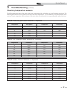
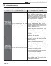
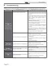
Condensate
Drain Blocked
(will require a manual
reset once condition has
been corrected. Press
the RESET button on
the display to reset.)
The blocked drain switch has detected
excessive condensate build up inside the
unit.
• Check condensate tube from unit to floor drain for
proper installation and obstructions.
• Inspect condensate trap for blockage. Clean if
necessary.
• Check for loose wiring connection at wire harness
plug.
• Bad blocked drain switch. Replace switch.
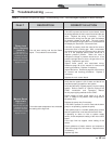
Flame out of
Sequence
(will require a manual
reset once the condition
has been corrected.
Press the RESET button
on the display to reset.)
The flame detector circuit is seeing a flame
signal while no flame is present.
• Check supply voltage for proper polarity.
• Check external wiring for voltage feedback.
• Check the flame rod and make sure it is clean.
• Check the internal wiring for bad connections.
• Replace main control board.
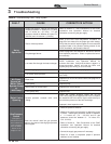
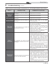
Gas Valve /
Connection
(will require a manual
reset once the condition
has been corrected.
Press the RESET button
on the display to reset.)
The main control board did not detect the
gas valve.
• Check wiring harness connection at the gas valve and
at the main control board.
• Replace the gas valve wire harness.
• Replace the gas valve.
• Replace the main control board.
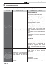
Burner Did Not
Light
(will require a manual
reset once the condition
has been corrected.
Press the RESET button
on the display to reset.)
The unit has failed to prove main burner
ignition after one attempt. It will require a
manual reset before attempting to fire again.
• Inspect spark electrode and associated wiring for
damage and connection. Reference page 39 of this
manual for removal and cleaning procedures.
Replace if necessary.
• Check for proper electrical grounding of the unit.
• Check incoming supply gas pressure. Natural gas
pressures should be between 4 - 14 inches w.c.
(1.0 - 3.5 kPa) and LP gas pressures should be
between 8 - 14 inches w.c. (2.0 - 3.2 kPa). Refer
to Section 6 - Gas Connections of the SYNC
Installation and Operation Manual for detailed
information concerning the gas supply.
• Verify that the plastic hose from the gas valve to the
air inlet is connected and is not damaged.
• Verify that the vent/air intake pipes are correctly
installed and that there are no obstructions.
• Check for 24 VAC to the gas valve at the 2-pin
connection on the side of the main control board
during the ignition attempt. If no voltage is present,
replace the main control board.
Service Manual
47