


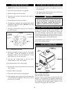


2. Using the view port, located below the water
connections, visually check main burner flames at each
start up after long shutdown periods or at least every six
months.
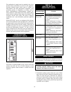
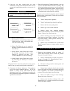
FIG. 4 Burner Flame Patterns
a. Normal Flame: A normal flame is blue, with
slight yellow tips, with a well defined inner
cone and no flame lifting.
b. Yellow Tip: Yellow tip can be caused by
blockage or partial obstruction of air flow to
the burner(s).
c. Yellow Flames: Yellow flames can be caused
by blockage of primary air flow to the
burner(s) or excessive gas input. This
condition MUST be corrected immediately.
d. Lifting Flames: Lifting flames can be caused
by over firing the burner(s) or excessive
primary air.
If improper flame is observed, examine the venting system,
ensure proper gas supply and adjust the combustion air.
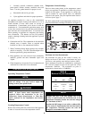
3. Combustion Air Shutter Adjustment: This appliance
uses a fan assisted combustion process. The fan air
shutter is factory pre-set and should not need
adjustment in most cases. If adjustment is required, the
fan air shutter may be manually adjusted to a dimension
specified for each model.
4. Flue Gas Passageways Cleaning Procedures: Any sign
of soot at the burners indicate a need for cleaning. The
following cleaning procedure must only be performed
by a qualified serviceman or installer. Proper service is
required to maintain safe operation. Properly installed
and adjusted units seldom need flue cleaning.
All gaskets on disassembled components must be replaced
with new gaskets on reassembly. Gasket kits are available
from your distributor.
a. Turn off main power to appliance.
b. Turn off main manual gas shutoff to appliance.
c. Remove the front outer jacket panels.
d. Remove gas valve from the manifold.
e. Remove screws from manifold mounting
brackets. Pull manifold(s) / orifice assembly away from
burners. Remove hose from burner tap.
f. Remove mounting screws from each burner and
slide burner out toward front of appliance. Use caution
to prevent damage to burner gaskets, refractory, hot
surface igniter or wiring.
g. Remove soot from burners with a stiff bristle
brush. Damaged burners or burner gaskets must be
replaced.
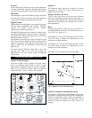
5. Check the heat exchanger surface for sooting. If
present, heat exchanger must be cleaned and problem
corrected. Proceed as follows.
a. Remove manifold/orifice assembly as described
in steps “a” through “e” in “Burner Removal” in the
Installation and Service Manual.
b. Disconnect wiring from hot surface igniter and
hose from burner tap.
c. Remove inner combustion chamber door mounting
screws, tilt slightly and slide door assembly out toward
front of appliance. Use caution to prevent damage to
refractory, hot surface igniter, hose and wiring.
d. Check "V" baffles on top of heat exchanger.
Remove and clean if necessary.
e. Remove soot from heat exchanger with a stiff
bristle brush. Use a vacuum to remove loose soot from
surfaces and inner chamber.
5
ƽƽ
WARNING
This area is hot and direct contact could result in
burns.
HEAT EXCHANGER CLEANING