


A-5
INSTALLATION
MAGNUM COOLER 10-I & 20-I
A-5
Cooler and insert the nipple into the connector nut so that the
threaded end of the connector nut points away from the barbed
end of the nipple. Twist the barbed end of the nipple into the
hose until the shoulder of the nipple is flush with the end of the
hose. Secure the hose onto the nipple with a hose clamp to
insure that the connection is water tight. No water can leak from
the connection if it is properly attached. Repeat the procedure for
the OUTLET hose. When complete, reference Figure 2 and fol-
low the connection procedure detailed below for connector nuts
that mate to the Magnum Cooler connector block.
For additional water lines that do not mate with Magnum Cooler
connections, order:
Order: (2) T15007-2 Connector Nuts*
(2) T15008 Nipples*
(2) S10888-35 Hose Clamps*
For all Lincoln products and those with a connector nut on the
water hose which mates with the connector block at the back of
a Magnum Cooler:
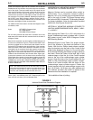
Save the two connector nuts and nipples provided with the unit
for future use. (Reference Figure 2). Take the water INLET hose
(colored or tagged blue on most hoses) and thread it into the
coolant OUT line located on the right hand side of the connector
block at the back of the Cooler. Secure the connector nut of the
hose tightly into the connector block with a wrench so that leak-
ing does not occur. Then take the OUTLET hose (colored or
tagged red on most hoses) and thread it into the coolant IN line
located on the left hand side of the connector block. Again, tight-
ly secure the connector nut of the hose into the connector block
of the Cooler with a wrench to insure that no leaking occurs. BE
CERTAIN THAT NO LEAKS EXIST WHEN COOLER IS
TURNED ON. A LEAK WILL DEPLETE RESERVOIR VOLUME,
CAUSE POOR OR COOLING PERFORMANCE AND REDUCE
GUN OR TORCH LIFE.
NOTE: Be certain that only 5/8-18 left hand male nuts with
clean and smooth threads are used on your water hoses. Poor
connections cause water to leak at connector block, down
hose lines, and eventually out the case sides of the unit.
* The connector and nipples listed fit tightly onto 4mm (5/32”) to
4.8mm (3/16”) inner diameter hose, but if clamped tightly to the
hose, can fit up to 6.4mm (1/4” inner diameter hose.
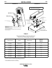
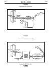
HORIZONTALLY MOUNTING MAGNUM COOLERS
ON LINCOLN TIG POWER SOURCES
Magnum Coolers can be mounted either upright or
horizontally. For a complete compact system,
Magnum 10-I or 20-I Cooler can be mounted horizon-
tally on the roof of Lincoln TIG Power Sources using
the optional K559-2 Horizontal TIG Mounting Bracket.
For proper installation, follow the instructions provided
with the kit. (See Figures 3a and 3b)
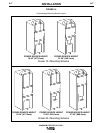
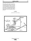
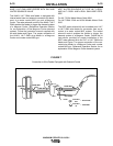
VERTICALLY MOUNTING MAGNUM COOLERS TO
LINCOLN UNDERCARRIAGES K874, K840-1*, K841-
1*, or K842-1*
When placing the Cooler 10-I or 20-I at the back of a
Lincoln Undercarriage used in tandem with a Lincoln
MIG power source, order K559-3 Magnum Cooler
MIG Mounting Bracket.
Reference Figure 3c and Table 2 for proper connec-
tion of the bracket to the back bolt pattern of the
Cooler. With the four Phillips head screws supplied,
align the bracket onto the back of the Cooler at the
proper holes displayed in Figure 3c. Do not fully tight-
en the bracket allowing the bracket to slightly move up
and down. Place the Cooler at the back right of the
undercarriage so that the lip of the Cooler bracket
rests on the top of the undercarriage upper cylinder
support. Align the holes of the Cooler bracket with the
holes on the undercarriage upper cylinder support.
Fasten the Cooler bracket with the holes on the
undercarriage upper cylinder support. Fasten the
Cooler bracket onto the undercarriage support with
both 1/4-20 bolts, 1/4-20 hex nuts, plain washers and
lock washers provided. Be certain to tighten all the
fasteners when the installation is complete.
* Not available at time of printing.
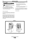
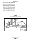
FIGURE 2
Inlet and Outlet Hose Connection Diagram
COOLANT
IN
COOLANT
OUT
FROM
HEAT
SOURCE
(RED)
TO
HEAT
SOURCE
(BLUE)