


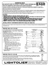

INSTALLATION OF SUSPENSION BEAM WITH CABLE OR STEM KITS (Cent’d.)
1S:6440
Paae 2 of
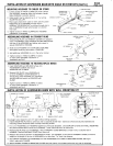
MOUNTING HOUSINGS TO CABLES OR STEMS
,
CABLE(ORSTEM)
1.
2.
3.
4.
Loosen screws in TRACK CLAMPS and insert clamps
AR
into HOUSING, engaging upper ribs between clamps.
Slide HOUSING to position desired.
Cable length may be adjusted up to ‘A” by
turning
WIREWAY
ADJUSTING COLLAR.
Pass supply leads (from cable or stem used for power
feed) along top of HOUSING, through hole in
WI REWAY COVER BRACKET and down through slot in
SLO
end of HOUSING through which power is to be fed
into track.
Tighten screws in TRACK CLAMPS after HOUSING
~v
SUPPLYLEADS
FIG. 2
installation is completed.
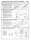
ASSEMBLING HOUSINGS IN STRAIGHT RUNS
“’m.:”” --Q. /
1.
2.
3.
4.
Remove END PLATE and WI REWAY COVER from adjacent
ends of HOUSINGS. Insert COUPLER and SPLINES halfway
into one of the HOUSINGS and tighten set screws to
secure COUPLER to HOUSING.
Slide second HOUSING onto COUPLER and SPLINES
and tighten remaining set screws in COUPLER.
Add additional HOUSINGS to run in the same manner.
Tighten screws in
TRACK CLAMPS of cables
or stems after HOUSING installation is
completed, see Fig.2
!-. -.-, “,
(-’’”
,...,.
...,-~
.....-.
cOuqRT‘ ‘>
SET SCREW
1
91
“2ss’L’NE&
HOUSING Q
J,
END PLATE
_A-.
(discard)
FIG. 3
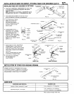
ASSEMBLING HOUSINGS TO HOUSING/SPLICE BOXES
1.
2.
3.
Insert COUPLERS and SPLINES halfway into
HOUSINGK3PLICE BOX and secure
COUPLERS with CLAMPS.
COUPLER-
Remove END PLATE from HOUSING and
v’
7
re-mount WI REWAY COVER BRACKET to
A
CLAMP—N~% ,,
second hole. Slide HOUSING onto COUPLER
and SPLINES and secure to COUPLER with
,.
CLAMP.
Tighten screws in TRACK CLAMPS of cables
or stems after HOUSING installation is
completed, see Fig. 2.
HOUSINGISPLICE —
BOX
INSTALLATION OF SUSPENSION BEAM WITH WALL MOUNTING KIT
SCREW (not furnished)
\d “RE’’’:VER =IU:IEI I“’=;;”
k END PLATE (di~~~~rj)
FIG. 5 L
BRANCH CIRCUIT LEADS
(L
(
MOUNTING PLATE
‘w /’”- CUMP
T
-
a
%
.\
.,’1
,~”,.. ‘
\b +
...
,+
*.
v
HOUSING
/
FIG. 6
For straight runs. SuppOrtS up to 12’ span without ceiling supports.
1. Fasten MOUNTING PLATES to outlet box and to opposite parallel wall. Outlet box should be securely fastened and
mounting surface should be solid to accept mounting screws.
2. In a run of HOUSINGS, join HOUSING together as previously described. Use COUPLER furnished with WALL MOUNTING
KIT (discard COUPLER furnished with HOUSING). Install COUPLER with flat side down.
3. Remove END PLATES from HOUSING(S). Mount WI REWAY COVER BRACKET, at feed-in end, to second hole in
HOUSING. Remove WI REWAY COVER from other end.
4. Measure the distance between the MOUNTING PLATES. Cut HOUSING, at end without WI REWAY COVER, so that its
length (or the length of the run of HOUSINGS) is not less than
3/16” than this distance.
5. Slip CANOPY COVERS onto HOUSING(S) and twist HOUSING(S) onto TABS on MOUNTING PLATES, see Fig. 6.
Lock in place with CLAMPS.
6. Mount CANOPY COVERS to MOUNTING PLATES and pull branch circuit leads (solid wire only) out of outlet box.
..
—.
..-