


I
—-
-
SUSPENSION BEAM
INSTRUCTION SHEET NO.
FOR USE WITH BASIC OR ADVENT LYTESPAN@ TRACK SYSTEMS ONLY
IS:6440
READ AND UNDERSTAND THESE INSTRUCTIONS BEFORE PROCEEDING.
R0790
Page 1 of 4
This fixture is intended for installation in accordance with the National Electrical Code and local regulations. TO assure full
compliance with local codes and regulations, check with your local electrical inspector before installation. To prevent electrical
shock, turn off electricity at fuse box before proceeding.
Retain these instructions for maintenance rafaranca.
Suspension Beam is a system of extruded aluminum housings which enclose Basic Lytespan (1 circuit) or Advent Lytespan (2 circuit)
Track. The housings may be used individually, in continuous runs or in a variety of patterns. They may be suspended on cables or
stems. They may also be mounted wall to wall without ceiling supports in spans up to 12’.
The housings may be cut, but must be straight and square. The cut end of a housing may be attached to another housing or to a
housing/splice box. Power cannot be fed into the cut end of a housing from a cable or stem kit.
CAUTION:
● TURN OFF POWER AT FUSE BOX BEFORE INSTALLING TRACK.
Q INSTRUCTIONS FOR GROUNDING PER INSTRUCTION SHEET OF THE FEED-IN KIT MUST BE FOLLOWED.
FAIIAJRElU DO SO MAY RESULT IN A HAZARDOUS CONDITION.
● DO NOT SUPPLY ADVENT TRACK FROM TWO SEPARATE 120V BRANCH CiRCU#TS AS THIS COULD
OVERLOAD THE NEUTRAL TRACK CONDUCTOR LEADING TO AN ELECTRICAL SAFETY HAZARD.
● OBSERVE POLARITY, WHITE SUPPLY LEAD (NEUTRAL) lQ CONTACT ON B@ADSIDE OF TRACK.
● REFER TO LOAD DATA, PAGE 4, FOR MAXIMUM SUSPENSION BEAM LOADING.
INSTALLATION OF SUSPENSION BEAM WITH CABLE OR STEM KITS
Power may be fed from cables or stems through either end of straight run of housings, including the end of a housing attached to a
housing/splice box.
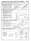
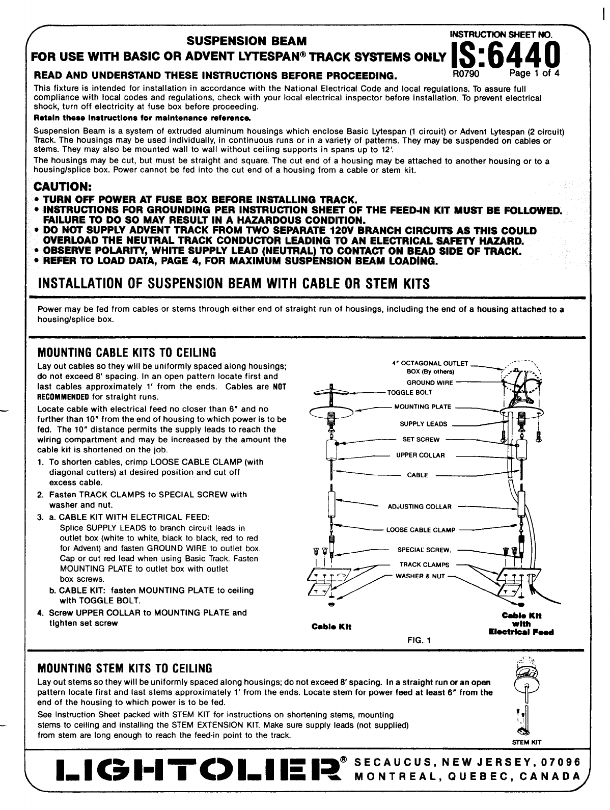
MOUNTING CABLE KITS TO CEILING
Lay out cables so they will be uniformly spaced along housings;
4’ OCTAGONAL OUTLET
.. . . . . .
do not exceed 8’ spacing. In an open pattern locate first and
eox (eyothers)
:.,’
iast cables approximately 1’ from the ends. Cables are
NOT
&
GROUNO WIRE
RECOMMENOEOfor straight runs.
_
TOGGLE eOLT
Locate cabie with electrical feed no closer than 6“ and no
~
MOUNTING PLATE ~ 1
further than 10” from the end of housing to which power is to be
fed. The 10” distance permits the supply leads to reach the
SUPPLY LEADS
wiring compartment and may be increased by the amount the
?
~ s~ SCREW
cable kit is shortened on the job.
1. To shorten cables, crimp LOOSE CABLE CLAMP (with
~ UPPERCOLLAR
diagonal cutters) at desired position and cut off ~ cAeLE
excess cable.
2. Fasten TRACK CLAMPS to SPECIAL SCREW with
washer and nut.
ADJUSTING COLLAR ~.
3. a. CABLE KiT WITH ELECTRICAL FEED:
Splice SUPPLY LEADS to branch circuit leads in
outlet box (white to white, black to black, red to red
for Advent) and fasten GROUND WIRE to outlet box.
Cap or cut red lead when using Basic Track, Fasten
yy
~ ‘pEC’AL ‘CRW”
MOUNTING PLATE to outlet box with outlet
box screws.
b. CABLE KiT fasten MOUNTiNG PLATE to ceiling
with TOGGLE BOLT.
e
4. Screw UPPER COLLAR to MOUNTiNG PLATE and
Cablo Klt
tighten set screw
Cabio Kit
With
Rlootrical hod
FIG. 1
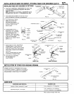
MOUNTING STEM KITS TO CEILING
,j:.T.~:,
,.
?
Lay out stems so they will be uniformly spaced along housings; do not exceed 8’ spacing. in a straight run or an open
pattern locate first and last stems approximately 1‘ from the ends. Locate stem for power feed at ieast 6“ from the
end of the housing to which power is to be fed.
See Instruction Sheet packed with STEM KIT for instructions on shortening stems, mounting
J
!!
stems to ceiling and installing the STEM EXTENSION KIT. Make sure supply leads (not supplied)
‘1
from stem are long enough to reach the feed-in point to the track.
STEM KIT
1- I <51-1709-1 Is 1?” :Y:::::L,N::::::,E:i::::