


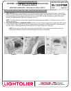

INTEGRAL SWITCH/INDICATOR LIGHT TO REFLECTOR MOUNTING: (1101F2642UEL)
1. With fixture mounted in ceiling, bring test switch and socket cup (2 separate conduits) through aperture hole in ceiling.
2. Remove nut from test switch connector and insert connector through 7/8” hole on reflector.
3. Fix test switch to reflector by securing nut to test switch connector. Attach socket cup to trim.
ADDITIONAL INSTALLATION INSTRUCTIONS FOR LUMINAIRES WITH EMERGENCY BACKUP
When installing or servicing LUMINAIRES equipped with EMERGENCY BACKUP, basic safety precautions should
always be followed including the following:
1. Do not install insulation above or within 3” (76mm) of any part of luminaire.
2. Turn off AC power before proceeding.
3. Be sure all electrical connections are complete before Unit Connector (located in the JUNCTION BOX) is connected.
4. Do not use outdoors.
5. Do not let power supply cords touch hot surfaces.
6. Do not mount near gas or electric heaters.
7. Use caution when servicing. Do not incinerate or mutilate; may burst or release toxic material. Do not short circuit; may cause
burns. Battery acid can cause burns to skin and eyes. If acid is spilled on skin or eyes, flush acid with fresh water and contact a
physician immediately.
8. Equipment should be mounted in locations and at a height where it will not readily be subjected to tampering by unauthorized
personnel.
9. The use of accessory equipment not recommended by the manufacturer may cause an unsafe condition.
10. Do not use this equipment for other than intended use.
11. This unit has more than one power supply connection point. To reduce the risk of electric shock – disconnect both normal and
emergency power supplies before servicing.
12. Before servicing, to prevent electric shock, make sure the unit connection of the EMERGENCY PACK (located in the JUNCTION
BOX) is disconnected, make certain that the switched (if the luminaire is switched) and the un-switched line to the EMERGENCY
PACK is turned off at the main power supply.
SERVICING SHOULD BE PERFORMED BY QUALIFIED SERVICE PERSONNEL ONLY.
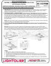
SWITCH/INDICATOR LIGHT BOX MOUNTING:
1. Cut 2-5/8” x 3-3/4” (66.7mm x 95.3mm) hole in ceiling/ceiling tile for Switch/Indicator Light box.
2. Pull down Switch/Indicator Light box and clamp onto ceiling by tightening screws on side of box. (Figure A)
3. Fasten Trim Plate to Switch box with nut provided. (Figure B)
Figure A
Figure B
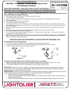
OPERATION: When the A.C. power is applied, the charging indicator light is illuminated, indicating that the battery is
being charged. When the power fails, the emergency lighting ballast automatically switches to emergency operation,
keeping one lamp on reduced output for 90 minutes.
MAINTENANCE: Although no routine maintenance is required to keep the emergency lighting ballast functional, it should
be checked periodically to ensure that it is working. The following schedule is recommended.
1. Visually inspect the charging indicator light monthly.
2. It should be illuminated. Test the emergency operation of the luminaire once every 3 months. One lamp should
operate at reduced output.
3. Conduct a 90 minute discharge test once a year. One lamp should operate at reduced output for 90 minutes.
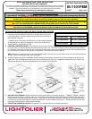
INSTALLATION PROCEDURE FOR:
1001FEM, 1101FEM and 1101FEL Series Frame-In Kits
with Emergency Backup
IMPORTANT SAFEGUARDS
–
READ AND FOLLOW ALL SAFETY INSTRUCTIONS
INSTRUCTION SHEET NO.
IS:1101FEM
D1007
Page 4 of 4
A COMPANY
631 Airport Road, Fall River, MA 02720