


INSTALLATION INSTRUCTIONS FOR WOOD FRAME CEILING APPLICATIONS
1
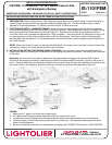
PREPARATION: Remove Wing Nuts on T-Bar Clips and remove clips from Luminaire Frame. Loosen Wing Nuts on
Frame Clamps enough to allow free movement of Mounting Bars (Figure A). The Mounting Bars may be readily
adjusted to fit openings between 13” (330mm) minimum and 24” (610mm) maximum.
2
POSITION AND INSTALL LUMINAIRE FRAME: Position Luminaire Frame between joists with the End bracket at
one end placed against, and flush to the bottom of, the joist (Figure B). When positioned, hammer the integral nailing
tabs at both ends of the End bracket into the joist (Figure C). Extend the End bracket at the opposite end of the
Luminaire Frame until it contacts the opposite joist. Align and attach. The frame can be fully secured by driving a nail
or screw through any of the holes provided at each end of the End bracket. Slide the Luminaire Frame along the
Mounting Bars until the aperture is in the desired position and lock the Frame in place by tightening the Wing Nuts on
the Frame Clamps.
NOTE: When the Luminaire Frame is to be used with Wall Wash Trims make sure to orient the Luminaire Frame side
indicated by a label on the frame towards the wall to be illuminated.
*
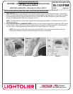
INSTALLATION OPTION FOR REGIONS USING STRAPPING: The Luminaire Frame may be installed directly to
strapping as above by screwing the End Bracket to the strapping using the hole provided. The Nailing Tab is not used
in this case.
Optionally, the Luminaire Frame may be attached to the joists between strapping, and positioned 5/8” lower to
account for the strapping thickness, by bending the provided End bracket tabs 90˚ as shown (Figure D) with a pair of
pliers. These bent tabs may now be used to position the Luminaire Frame vertically with reference to the joists so that
the frame is flush to the strapping. Attach the Luminaire Frame to the joists as described above (Figure E).
Figure A
Figure B
Figure C
Figure D
Figure E
WIRING:
1. Make sure A.C. power is off at the main power supply.
2. A.C. Ballast and Emergency Ballast must be fed from the same branch circuit.
3. In switched luminaire installations the Emergency Ballast must be connected ahead of any local switching.
4. Check markings on fixture before making connections in junction box. See additional battery pack instruction
sheet for wiring diagrams.
5. Be sure all electrical connections are made before connecting UNIT CONNECTOR located in JUNCTION BOX.
INSTALLATION PROCEDURE FOR:
1001FEM, 1101FEM and 1101FEL Series Frame-In Kits
with Emergency Backup
IMPORTANT SAFEGUARDS
–
READ AND FOLLOW ALL SAFETY INSTRUCTIONS
INSTRUCTION SHEET NO.
IS:1101FEM
D1007
Page 2 of 4
A COMPANY
631 Air
p
ort Road
,
Fall River
,
MA 02720