


INSTALLATION INSTRUCTIONS FOR GRID CEILING APPLICATIONS
1
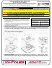
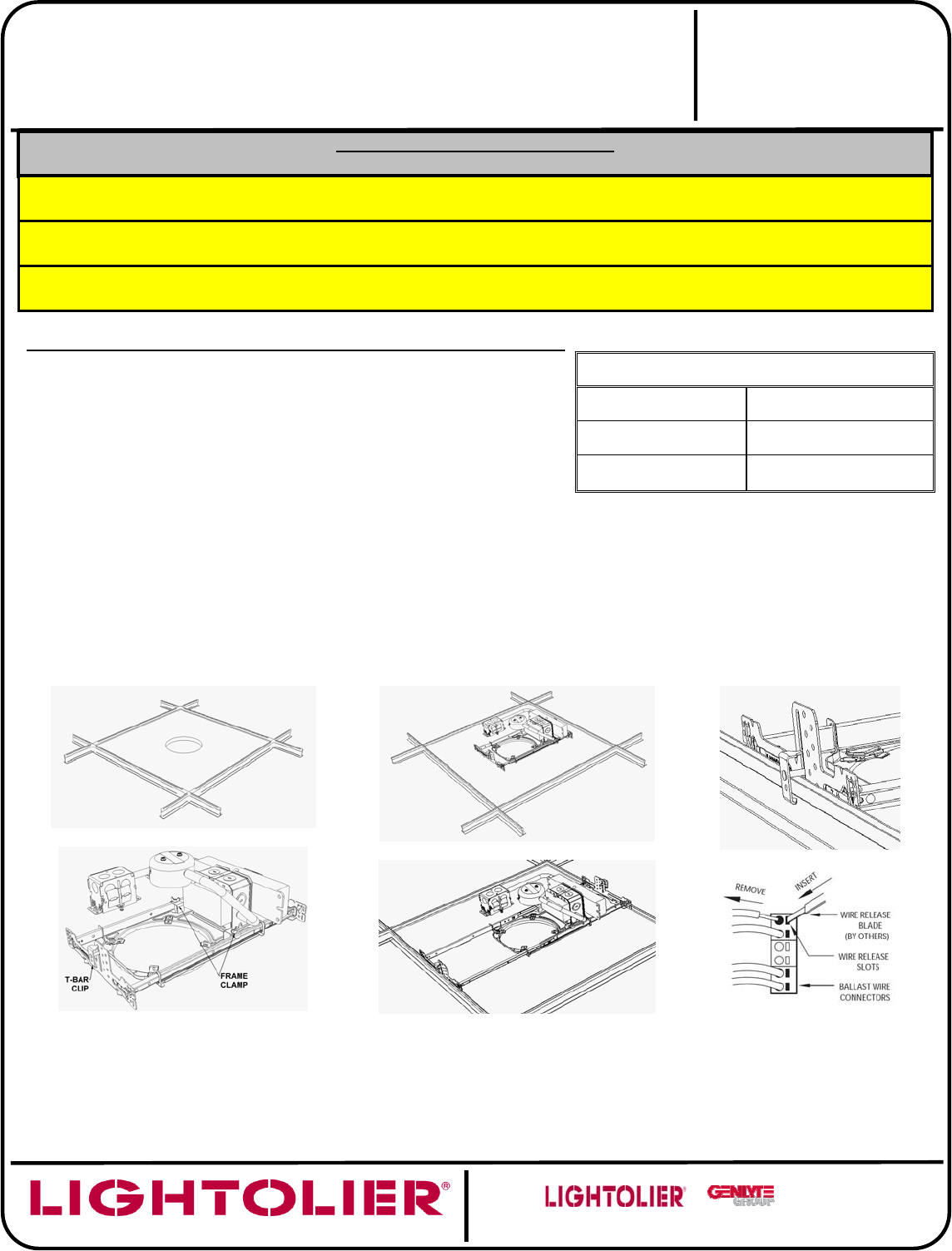
PREPARATION: Cut appropriately sized hole in Ceiling Tile (by others) at
the position desired and place Ceiling Tile in Grid (by others) (Figure A).
Loosen Wing Nuts on Frame Clamps enough to allow free movement of
Mounting Bars (Figure B).
* Lightolier offers a hole cutter (HC-356) that can be purchased separately
to assist with quick, clean trim installations. In this case, follow the hole
cutting directions supplied with HC-356.
APERTURE HOLE SIZE
1001FEM SERIES 5-1/4” (134mm) DIA
1101FEM SERIES 6-15/16” (176mm) DIA
1101FEL SERIES 6-15/16” (176mm) DIA
2
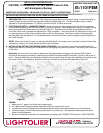
POSITION LUMINAIRE FRAME: Place Luminaire Frame on top of Ceiling Tile and center the frame aperture on the Ceiling Tile
hole cut in Step 1 so that the aperture wall extends into the Ceiling Tile. Orient the Luminaire Frame to align with the grid (Figure
C). Grasp the T-Bar Clips on each end, one in each hand, lift the clips to the top of the adjustment slots in the End bracket, extend
the End brackets to contact the Ceiling Grid, and drop each T-Bar Clip over the Grid (Figure D).
NOTE: When the Luminaire Frame is to be used with Wall Wash Trims make sure to orient the Luminaire Frame side indicated by
a label on the frame towards the wall to be illuminated.
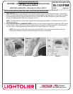
3
CLAMP TO GRID and LOCK LUMINAIRE FRAME: Making certain that the Luminaire Frame is still centered on the Ceiling Tile,
tighten the T-Bar Clip Wing Nuts to attach the frame to the Ceiling Grid (Figure E). Retighten the Wing Nuts on the Frame Lock
Clamps after the frame is positioned satisfactorily and is locked to the Ceiling Grid.
Figure A
Figure B
Figure C
Figure D
Figure E
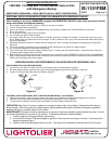
Figure F
*
BALLAST REPLACEMENT: Ballast replacement must be performed by a “qualified electrician”. TURN OFF POWER. Remove
reflector trim from luminaire. Remove j-box cover nearest the ceiling opening to which the ballast is mounted by lifting the spring.
Remove ballast assembly through the ceiling hole. Disconnect all input wiring to the ballast. Release all wires from ballast wire
connectors by inserting small blade tool, with insulated handle, into wire release slots (Figure F). Remove ballast from j-box door
and replace with new ballast. Rewire and reassemble.
*
REFLECTOR TRIM INSTALLATION: See separate Trim Instruction Sheet for installation procedure.
READ AND UNDERSTAND THESE INSTRUCTIONS
BEFORE INSTALLING LUMINAIRE.
This luminaire is intended for installation in accordance with the National Electrical Code and local regulations.
To assure full compliance with local codes and regulations, check with your local electrical inspector before
installation. To prevent electric shock, turn off electricity at main power supply before proceeding.
Retain these instructions for maintenance reference.
INSTALLATION PROCEDURE FOR:
L
y
tecaster
®
1001FEM, 1101FEM and 1101FEL Series Frame-In Kits with Emer
g
enc
y
Backu
p
CAUTION: (RISK OF FIRE) THIS IS A NON-IC RATED FRAME-IN KIT.
DO NOT INSTALL INSULATION ABOVE OR WITHIN 3 INCHES (76mm) OF ANY PART OF LUMINAIRE.
CAUTION: USE ONLY WITH REFLECTOR TRIMS PROVIDED BY LIGHTOLIER. USE OF OTHER MANUFACTURER’S TRIMS
MAY VOID THE UNDERWRITERS LABORATORIES LISTING AND COULD CONSTITUTE A FIRE HAZARD.
INSTRUCTION SHEET NO.
IS:1101FEM
D1007
Page 1 of 4
A COMPANY
631 Air
p
ort Road
,
Fall River
,
MA 02720
CAUTION: BEFORE INSTALLING FRAME-IN KIT AND REFLECTOR TRIM, READ ALL MARKINGS ON FRAME-IN KIT AND
REFLECTOR TO DETERMINE LAMP WATTAGE AND TYPE APPLICABLE FOR YOUR INSTALLATION.