


9
NOTE: DIAGRAMS & ILLUSTRATIONS ARE NOT TO SCALE.
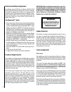
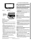
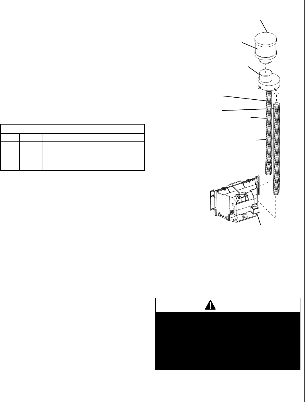
vertiCal venting
The vent pipes must be connected to the proper collars on
the unit and the exhaust vent pipe must be connected to the
termination cap or the unit will not operate. The combustion
air vent pipe can be connected to the termination cap or it
can terminate inside the chimney.
The bottom opening of the chimney must be sealed around
the vent pipes if the combustion air vent is not connected
to the termination cap. Use unfaced fiberglass insulation to
seal around the vent pipes. The insulation may give off an
odor during the first hour of operation.
NOTE: The minimum vertical rise (exhaust vent) is 10 feet
(3.1 M) and the maximum vertical rise is 35 feet (10.7 M).
These dimensions are measured from the starting collars
of the unit to the end of the vent pipe.
The fireplace and fireplace chimney must be clean and in good
working order and constructed of non-combustible materials.
Inspect chimney cleanouts for proper fit and seal.
* Other approved vent components include; Standard Simpson Dura-vent Co-linear
Chimney Liner Kit, Direct Vent Termination #991, Liner Termination Kit (includes
termination connector and flashing) #923GK & 3" x 35' Alum Flex #2280
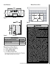
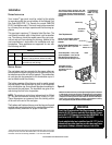
Vertical Cap
Termination
Connector
Exhaust
Intake
Combustion Air Intake
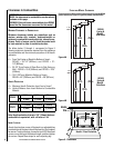
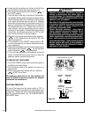
The existing fireplace chimneys may take
various contours which the flexible liners will
accommodate. However, keep the flexible liner
as STRAIGHT as possible, avoid unnecessary
bending.
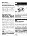
Liner Requirements:
Vertical Height Min. = 10 ft. (3.1 M)
Vertical height Max. = 35 ft. (10.7 M)
Note: Measured from flue collar on
unit to the end of the vent pipe or liner
Use 3" (76 mm) diameter listed gas
vent liner (UL1777 ONLY) for the
EXHAUST
Use 3" (76 mm) diameter listed
liner (UL 181 or UL1777) for the
AIR INTAKE.
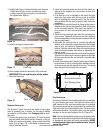
The flexible vent pipe
must NOT be allowed to
sag behind insert or in
fireplace flue.
The standard cap
in Termination Kit,
H0908, is a high
wind cap
Make sure that both liners will pass through existing damper area. Remove
or lock damper to allow the passage of the flexible liners. If the damper
will not allow the passage of both liners, DO NOT PROCEED FURTHER.
(If fireplace is masonry) Consult a local mason for removal of the damper
without risk of structural damage or leakage (if the fireplace is factory
built) The appliance may NOT be installed into the fireplace.
WARNING
Direct-Vent Fireplace Insert Vent Requirements - Use liner
listed to UL181 (Factory-made Air Ducts And Air Connec-
tors) or UL1777 (Chimney Liners) for the AIR INTAKE. Use
liner listed to UL1777 ONLY for the EXHAUST.
Do not substitute the heat-rated flex liner (UL1777) for the
exhaust with any other type liner or a fire may result caus-
ing property damage, personal injury or loss of life.
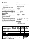
Vent Kits *
Cat. No. Model Description
H0909 FKDVI Flex Liner Kit, DVI 3” X 35’
(requires 2, one for exhaust, and one for intake)
H0908 TKDVI Termination Kit, DVI
(termination cap and flashing)
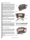
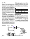
Installation
venting installation
Your Lennox™ gas insert must be vented to the outside
in accordance with the current edition of the National Fuel
Gas Code ANSI-Z223.1 (In Canada, the current CAN/CSA
B149.1 installation code). The insert must not be connected
to a chimney flue serving a separate solid fuel burning ap
-
pliance.
This gas insert requires a 3” diameter listed flex liner. The
vent should terminate with a listed direct vent termination
cap. The chimney should be sealed around the cap to pre
-
vent air and rain from entering the chimney. Adhere to the
vent manufacturer's instructions for installation and vent
termination. These appliances are approved for use with
the following vent kits.
Figure 6