


16
NOTE: DIAGRAMS & ILLUSTRATIONS ARE NOT TO SCALE.
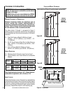
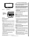
operating options
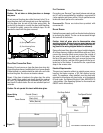
The rocker switch on your Ravenna™ gas insert is used to
turn the burner on and off while the pilot is on. The rocker
switch can be installed in the hole in the right side of the
top surround panel or in the hole in the panel to the left
of the igniter button. The hole in the panel is covered by a
label which must be carefully cut out before installing the
rocker switch. The switch must be disconnected from the
coil of wire to which it is attached, the plastic nut unscrewed
from the back side of the switch, and then the switch can
be inserted into the hole at either location. If the switch is
to be located in the surround, route the wire behind the
igniter bracket and through the hole in the lower right side
of the insert. Attach the three plastic adhesive wire restraints
(found in the bag in the firebox) to the side surround panel.
Feed the wire through these restraints and up to the switch.
Care should be taken to ensure the wire does not come in
contact with the hot surfaces of the firebox. Reconnect the
wires to the switch.
A wall-mounted switch, a millivolt wall thermostat, or a
remote control, can be used to supplement the rocker
switch. The gas valve is powered by millivolts generated by
the pilot assembly. This millivolt system is very sensitive to
electrical resistance, therefore, make sure all connections
are tight, clean, and free from corrosion. Do not splice any
millivolt wires. Consult the table on this Page to determine
the proper gage of wire for the thermostat or wall switch
connections. This table refers to the total length of the wire
(out to the switch and back). The thermostat must be a
millivolt type. A 24-volt furnace thermostat will not work.
Never hook up household current - 120 Volts - to the mil
-
livolt system. It is not recommended to hook up any more
than two switches to the insert (for example a rocker switch
and a wall thermostat). Additional switches may affect the
system resistance and increase the chance of the burner not
igniting. Follow the instructions included with the thermostat
or remote control for wiring.
The thermostat, remote control, and rocker switch will turn
the burner on and off independently. Be sure to set the rocker
switch to the “OFF” position when using the thermostat or
remote control and set the thermostat or remote control to
the lowest temperature when you wish to use the rocker
switch only, otherwise one may override the other. If a re
-
mote thermostat is to be used with the insert, do not place
the receiver under the firebox.
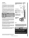
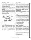
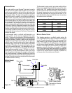
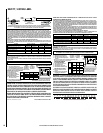
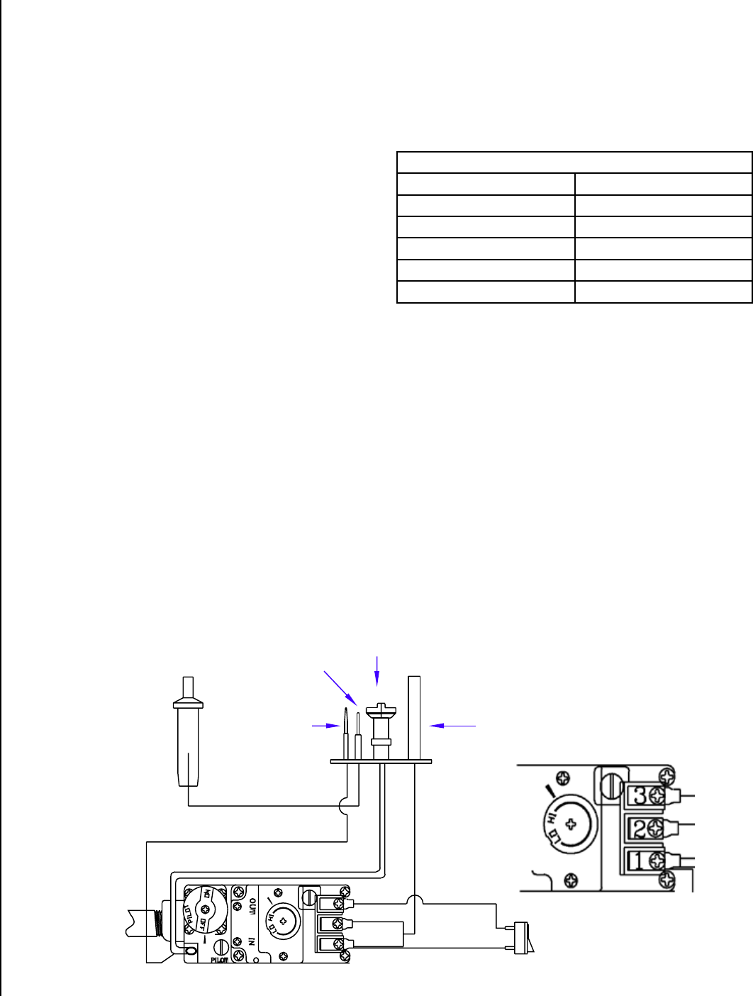
Millivolt Control
Schematic
Sparker
Pilot Hood
ON/OFF Rocker Switch,
Thermostat, or Remote
Thermostat
Pilot Assembly
Thermocouple
Piezo Igniter
White
Gas Inlet
Pilot Gas Line
Thermopile
Wiring Terminals
Brown
Thermostat Wire
Wire Size Maximum Length
12 Gage
100 Feet
14 Gage 64 Feet
16 Gage
40 Feet
18 Gage 25 Feet
20 Gage 16 Feet
millivolt Control system
This fireplace operates on a millivolt control system. As
such, no additional power supply is needed for the fireplace
to heat. The pilot assembly contains a thermocouple, that
when heated by the pilot flame, generates electricity (mil
-
livolts- mV=1/1000 of a volt) which opens a valve allowing
gas to flow to the pilot assembly. The pilot assembly also
contains a thermopile, that when heated by the pilot flame,
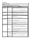
generates electricity that flows to terminal #1 (labeled
THTP) on the gas valve. When the electricity is conducted
from terminal #1 through the on/off switch, thermostat, or
receiver of the remote control to terminal #3 (labeled TH)
on the gas valve, the main burner will ignite.
Figure 18
TH
TP
TH/TP