


Page 9
XC14 SERIES
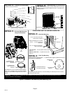
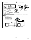
ROOF MOUNTING
Install the unit a minimum of 6 inches (152 mm) above the
roof surface to avoid ice build−up around the unit. Locate
the unit above a load bearing wall or area of the roof that
can adequately support the unit. Consult local codes for
rooftop applications.
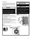
NOTICE
Roof Damage!
This system contains both refrigerant and oil. Some
rubber roofing material may absorb oil and cause the
rubber to swell when it comes into contact with oil. The
rubber will then bubble and could cause leaks. Protect
the roof surface to avoid exposure to refrigerant and oil
during service and installation. Failure to follow this
notice could result in damage to roof surface.
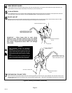
Removing and Installing Panels
IMPORTANT
Do not allow panels to hang on unit by top tab. Tab is for
alignment and not designed to support weight of panel.
WARNING
To prevent personal injury, or damage to panels, unit or
structure, be sure to observe the following:
While installing or servicing this unit, carefully stow all
removed panels out of the way, so that the panels will not
cause injury to personnel, nor cause damage to objects
or structures nearby, nor will the panels be subjected to
damage (e.g., being bent or scratched).
While handling or stowing the panels, consider any
weather conditions, especially windy conditions, that
may cause panels to be blown around and battered.
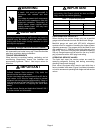
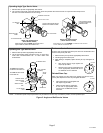
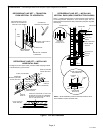
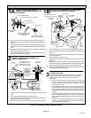
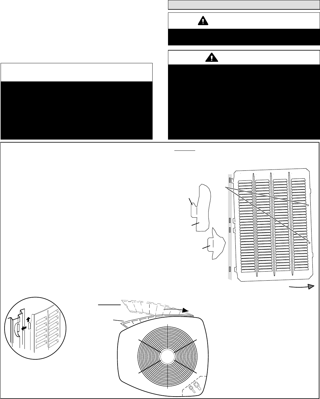
LOUVERED PANEL REMOVAL
Remove the louvered panels as follows:
1. Remove two screws, allowing the panel to swing open slightly.
2. Hold the panel firmly throughout this procedure. Rotate bottom corner of
panel away from hinged corner post until lower three tabs clear the slots as
illustrated in detail B.
3. Move panel down until lip of upper tab clears the top slot in corner post as
illustrated in detail A.
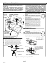
LOUVERED PANEL INSTALLATION
Position the panel almost parallel with the unit as illustrated in detail D with the
screw side as close to the unit as possible. Then, in a continuous motion:
1. Slightly rotate and guide the lip of top tab inward as illustrated in detail A and
C; then upward into the top slot of the hinge corner post.
2. Rotate panel to vertical to fully engage all tabs.
3. Holding the panel’s hinged side firmly in place, close the right−hand side of
the panel, aligning the screw holes.
4. When panel is correctly positioned and aligned, insert the screws and
tighten.
DETAIL A
DETAIL B
ROTATE IN THIS DIRECTION;
THEN DOWN TO REMOVE
PANEL
SCREW
HOLES
LIP
IMPORTANT! DO NOT ALLOW PANELS TO HANG ON UNIT BY TOP TAB. TAB IS FOR
ALIGNMENT AND NOT DESIGNED TO SUPPORT WEIGHT OF PANEL.
PANEL SHOWN SLIGHTLY ROTATED TO ALLOW TOP TAB TO EXIT (OR
ENTER) TOP SLOT FOR REMOVING (OR INSTALLING) PANEL.
MAINTAIN MINIMUM PANEL ANGLE (AS CLOSE TO PARALLEL
WITH THE UNIT AS POSSIBLE) WHILE INSTALLING PANEL.
PREFERRED ANGLE
FOR INSTALLATION
ANGLE MAY BE TOO
EXTREME
HOLD DOOR FIRMLY TO THE HINGED
SIDE TO MAINTAIN
FULLY−ENGAGED TABS
Detail C
Figure 6. Removing and Installing Panels