


Page 20
506636−01
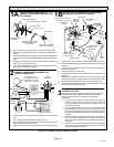
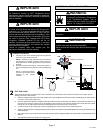
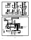
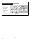
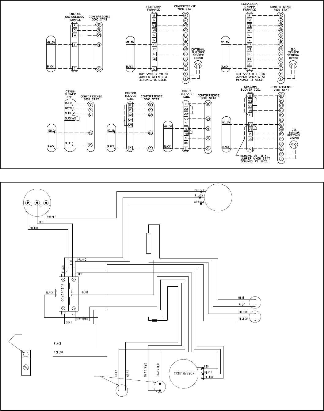
NOTE − Refer to furnace, blower coil and accessory instructions for additional wiring configurations with other
optional controls.
XC13
XC13 XC13
XC13
XC13
XC13
XC13
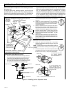
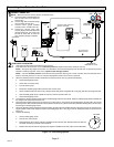
Figure 14. 24VAC Control Wiring Diagrams (Field Installed)
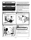
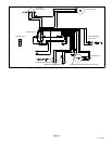
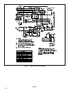
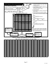
HIGH PRESSURE
SWITCH (S4)
CRANKCASE
THERMOSTAT
(S40)
CRANKCASE
HEATER (HR1)
DUAL RUN CAPACITOR
(C12)
FAN MOTOR (B4)
COMPRESSOR
(B1)
CONTACTOR
K1
−048 AND −060
ONLY
GROUND LUG
THERMAL PROTECTION
SWITCH (S5)
Figure 15. Typical Factory Wiring Diagram (Copeland Compressor)