


Page 28
506636−01
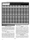
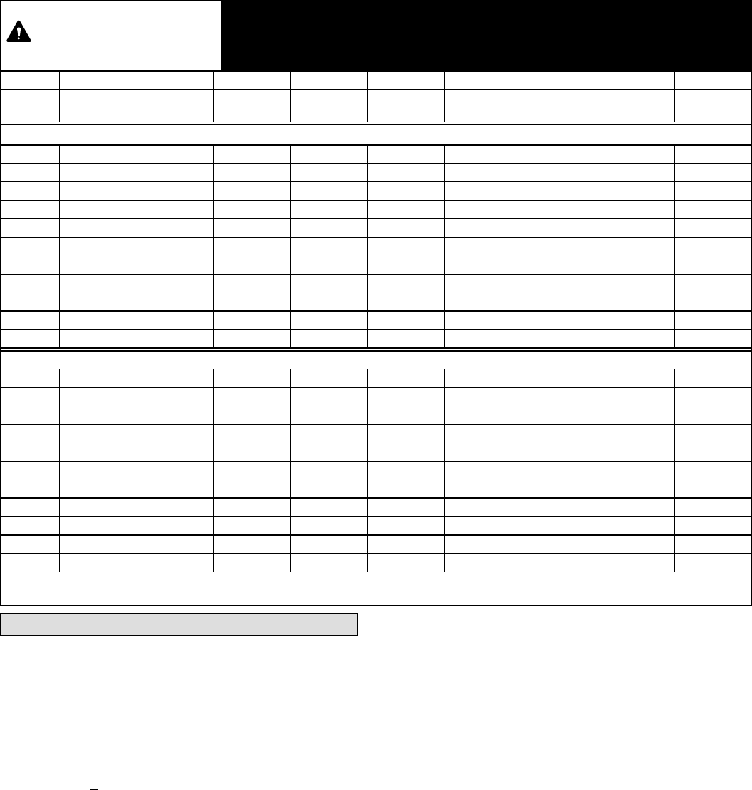
Table 4. Normal Operating Pressures (Liquid +10 and Suction +5 psig)
IMPORTANT
Use this table to perform maintenance checks; it is not a procedure for charging the
system. Minor variations in these pressures may be due to differences in installations.
Significant deviations could mean that the system is not properly charged or that a
problem exists with some component in the system.
Model −018 −024 −030 −036 −041 −042 −047 −048 −060
**Temp.
5F (5C)
Liquid /
Suction
Liquid /
Suction
Liquid /
Suction
Liquid /
Suction
Liquid /
Suction
Liquid /
Suction
Liquid /
Suction
Liquid /
Suction
Liquid /
Suction
Expansion Valve (TXV)
65 (18) 230 / 138 225 / 135 226 / 129 238 / 132 233 / 142 236 / 138 233 / 139 238 / 136 239 / 133
70 (21) 244 / 139 242 / 137 241 / 131 254 / 135 239 / 142 253 / 140 252 / 140 256 / 138 258 / 135
75 (24) 265 / 140 260 / 138 259 / 134 273 / 138 256 / 143 273 / 141 272 / 141 277 / 139 278 / 136
80 (27) 286 / 140 282 / 140 281 / 138 293 / 140 278 / 144 296 / 142 294 / 142 299 / 140 300 / 137
85 (29) 307 / 142 304 / 141 301 / 140 316 / 142 299 / 145 318 / 143 315 / 142 320 / 139 323 / 138
90 (32) 330 / 143 326 / 142 324 / 141 340 / 143 321 / 145 341 / 144 338 / 144 343 / 140 346 / 139
95 (35) 351 / 144 351 / 142 348 / 142 366 / 144 343 / 146 366 / 146 361 / 144 369 / 141 370 / 140
100 (38) 380 / 144 376 / 144 372 / 143 392 / 145 366 / 147 392 / 147 387 / 144 395 / 142 396 / 142
105 (41) 407 / 145 403 / 145 399 / 144 420 / 147 389 / 148 417 / 148 413 / 145 422 / 144 415 / 143
110 (43) 436 / 146 433 / 145 428 / 145 449 / 148 421 / 149 445 / 149 442 / 148 450 / 146 449 / 145
115 (45) 466 / 147 463 / 147 456 / 146 480 / 149 452 / 151 475 / 151 465 / 148 481 / 148 476 / 147
Fixed Orifice (RFC)
65 (18) 232 / 124 228 / 125 229 / 128 241 / 131 228 / 131 248 / 135 232 / 125 240 / 126 244 / 125
70 (21) 248 / 127 244 / 127 243 / 129 258 / 134 245 / 135 266 / 138 249 / 129 260 / 129 263 / 128
75 (24) 267 / 131 261 / 131 261 / 132 277 / 136 263 / 138 285 / 141 268 / 133 281 / 133 281 / 131
80 (27) 286 / 135 284 / 134 284 / 135 298 / 139 284 / 141 305 / 143 286 / 136 301 / 135 303 / 134
85 (29) 307 / 138 303 / 137 305 / 138 321 / 141 306 / 144 327 / 145 312 / 140 324 / 138 324 / 136
90 (32) 328 / 141 325 / 140 327 / 140 342 / 143 327 / 146 349 / 147 332 / 142 346 / 140 347 / 139
95 (35) 351 / 143 347 / 142 349 / 142 366 / 145 348 / 148 372 / 149 357 / 144 371 / 142 370 / 141
100 (38) 375 / 146 370 / 144 372 / 144 392 / 147 372 / 149 396 / 150 379 / 146 395 / 144 394 / 143
105 (41) 400 / 148 394 / 146 396 / 146 416 / 149 395 / 151 421 / 152 406 / 149 420 / 146 418 / 145
110 (43) 426 / 150 420 / 148 422 / 148 446 / 151 424 /153 447 / 153 430 / 150 447 / 148 444 / 146
115 (46) 457 / 153 447 / 150 449 / 150 480 / 152 453 / 155 476 / 154 460 / 152 473 / 150 471 / 147
*Values shown are typical pressures; indoor unit match up, indoor air quality equipment, and indoor load will cause the pressures to vary.
**Temperature of the air entering the outside coil.
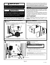
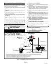
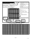
System Operation
UNIT COMPONENTS
High Pressure Switch (S4)
XC14 units are equipped with a high-pressure switch that
is located in the liquid line of the compressor as illustrated
in Unit Dimensions on page 2. The switch is a Single Pole,
Single Throw (SPST), manual−reset switch with red cap
that is normally closed and removes power from the
compressor when discharge pressure rises above factory
setting at 590 + 10 psi.
Thermal Protection Switch (S5) Ċ Discharge Line
Mounted
This unit is equipped with a discharge line mounted
temperature switch that prevents compressor damage
due to loss of charge. The switch is located on the
discharge line (see figure 1 for location). When the switch
senses a discharge line temperature of 220°F +/−5°F, it
opens to shut off compressor operation. The auto−reset
switch closes when the discharge line temperature drops
below 180°F +/−9°F and the compressor is re−energized.
This single−pole, single−throw (SPST) bi−metallic switch is
wired in series with the 24V Y input signal to control
compressor operation.
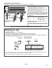
Thermal Protection Switch (S173) Ċ Compressor
Mounted
Some units are equipped with a compressor mounted
normally closed temperature switch that prevents
compressor damage due to overheating caused by
internal friction. The switch is located on top of the
compressor casing (see figure 1). This switch senses the
compressor casing temperature and opens at 239−257°F
(115°C−125°C) to shut off compressor operation. The
auto−reset switch closes when the compressor casing
temperature falls to 151−187°F (66°C−86°C), and the
compressor is re−energized. This single−pole, single−throw
(SPST) bi−metallic switch is wired in series with the 24V Y
input signal to control compressor operation.
Crankcase Thermostat (S40) (−041, −047, −048 and
−060 units only)
Compressor in the above reference units are equipped
with a 70 watt, belly band type crankcase heater. HR1
prevents liquid from accumulating in the compressor. HR1
is controlled by a thermostat located on the liquid line.