


Page 7
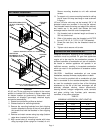
3- The air inlet diameter shall be 3” (76mm) on
45/60/75 units and 4” (100mm) on 100/125 units.
Refer to table 4 for diameter and termination
requirements.
4- Select a wall termination point that will maintain ¼”
rise per foot slope of horizontal run of vent pipe.
The vent may be single wall material minimum 26
GSG (0.46mm) galvanized steel or equivalent grade
stainless steel. Seal single wall vent material
according to the section A-General
Recommendations and Requirements. In areas
where local authorities having jurisdiction permit, a
downward slope of maximum ¼” per foot is also
acceptable. In such cases, the vent must be listed
special vent for Category III appliances or single
wall vent pipe constructed of number 26 GSG
(0.46mm) galvanized steel or equivalent grade
stainless steel. Seal single wall vent material
according to the section A-General
Recommendations and Requirements.
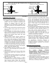
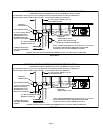
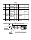
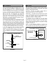
Condensate drainage can be collected in a tee pipe
section (figure 4) or allowed to drip through the vent
termination, if permitted by local authorities (figure
5).
5- For upward sloped vent a condensate tee and drain
must be installed within the first 5’ (1.5m) from the
unit heater to protect the appliance. If a flexible
condensate drain line is used, the drain line must
include a loop filled with water to prevent
combustion products from entering the structure. If
the unit is shut down for an extended period of time
and will be exposed to sub-freezing temperatures,
the condensate may freeze.
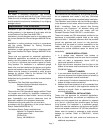
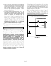
FIGURE 3
CONDENSATE DRAIN THROUGH TEE PIPE AND DRAIN LOOP
DRAIN LOOP WITH WATER
TRAP (TO CONDENSATE DRAIN)
LISTED THIMBLE
THROUGH
COMBUSTIBLE WALL
GROUND LEVEL
NOTE - MINIMUM HORIZONTAL LENGTH 3 FT. (91.4 CM) NOT
INCLUDING TERMINATION. REFER TO TABLE 2 FOR
MAXIMUM LENGTH AND NUMBER OF ELBOWS.
MAY BE SINGLE WALL (26 GSG) GALV. OR EQUIVALENT STAINLESS STEEL SEALED ACCORDING TO
THESE INSTALLATION INSTRUCTIONS. SLOPE:+ 1/4 INCH FOR 1 FOOT RUN MINIMUM.
UPWARD SLOPE ON HORIZONTAL VENT-COMMERCIAL INSTALLATION
COMMON VENTING NOT ALLOWED WHEN HORIZONTALLY VENTING THE UNIT HEATER.
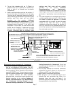
VENT TERMINATION
12” (30.5 CM) MIN. FROM WALL TO
VENT TERMINATION
12” (30.5 CM) MINIMUM ABOVE
HIGHEST SNOWFALL
(TERMINATIONS MAY
USE WIRE MESH BIRD
SCREEN)
AIR INLET
TERMINATION
12” (30.5 CM) MIN. FROM
AIR INLET TO VENT
TERMINATION (MAY
BE HORIZONTAL OR
VERTICAL CLEARANCE)
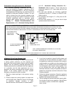
E-Horizontal Venting Concentric Kit - Commercial
1-Horizontal commercial installations are for buildings
that are not attached to living spaces. The only
concentric vent/adapter/cap kit that may be used is
the kit supplied by Lennox Industries. The kit may be
used with 45/60/75 units. The vent used to connect
from the concentric adapter to the unit may be single
wall material minimum 25 GSG (0.46mm)
galvanized steel or equivalent grade stainless steel
installed according to the sections Venting A-
General Recommendations and Requirements
and C-Horizontal Venting General and D-
Horizontal Venting–Commercial and E-Horizontal
Venting Concentric Kit - Commercial. The air inlet
may be single wall material or U.L. listed single wall
flex vent connector.
2-The vent pipe diameter for horizontal commercial
installations shall be 3” (76mm) on 45 units and 4”
(100mm) on 60/75 units. Refer to table 4.
3-Refer to table 2 for maximum vent lengths.
4-Refer to figure 7 for kit termination, figure 3 for
upward slope with condensate trap, figure 4 for
downward slope with trap, and figure 5 for
downward slope with condensate drain through cap
where permitted by local authorities.