


Page 16
To Turn Off Gas To Unit
1- Set thermostat to lowest level.
2- Turn off all electrical power to unit if service is to be
performed.
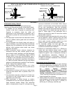
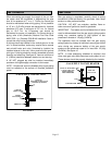
3- Honeywell VR8205 series valve: turn knob on gas
valve 90° clockwise
to OFF.
White Rodgers 36E series valves: turn knob on gas
valve 180° either way to OFF.
Robertshaw DER2000 series valves: depress knob
on gas valve; knob will snap to OFF.
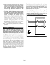
Heating Sequence of Operation
1- When the thermostat calls for heat, the combustion
air blower starts immediately.
2- Combustion air inducer proving switch proves
blower operation before allowing power to the
ignition controller. This switch is factory set and no
adjustment is necessary.
3- After prepurge of approximately 30 seconds, the
spark ignition is energized and the solenoid valves
open in the gas valve.
4- The spark then ignites the gas, the ignition sensor
proves the flame and the combustion process
continues.
5- In the event that the flame is not detected after the
first 10-second trial for ignition, the controller will
repeat steps 3 and 4 an additional two times before
locking out the gas valve. Ignition control will then
automatically repeat steps 3, 4, and 5 after 60
minutes.
To interrupt the 60-minute lockout period, move
thermostat from “Heat" to “OFF" then back to
“Heat." Heating sequence then restarts at step 1.
6- The burners shall light without noticeable crossover
delay. There shall be no flame lifting from the burner
heads, flashback or burning within the burner. The
flames shall be predominantly blue in color and
shall be approximately centered in the tubes with no
apparent impingement taking place.
7- The ignition control will energize the fan
approximately 45 seconds after ignition is
established.
8- After the thermostat demand is satisfied the gas
valve is closed; 5 seconds after the demand is
satisfied the combustion air blower is shut off.
9- The control center shall shut off the system fan
approximately 120 seconds after the gas valve is
de-energized.
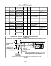
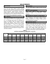
Ignition Control LED
The ignition control board contains a green LED which
indicates the following:
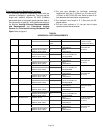
TABLE 5
IGNITION CONTROL LED
LED UNIT OPERATION
Slow
Flash*
Normal Operation - No call for heat
Fast
Flash
Normal Operation - Call for heat
Current signal at FLAME terminal 0.6 to 1.0 microamps
2 Flashes System lockout - failed to detect or sustain flame
Current signal at FLAME terminal <0.6 microamps
3 Flashes Combustion air inducer proving switch failed closed
before CAB is energized or failed open after CAB is
energized
4 Flashes High limit or rollout switch open
5 Flashes Flame sensed and gas valve not energized
Steady
Off
Loss of power
Steady
On
Ignition control failure
*When thermostat is placed in continuous fan mode LED will
slowly flash.
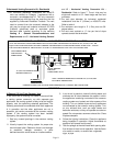
Optional Gas Conversion Kit
A natural to LP/propane gas changeover kit is required
to convert unit. Refer to the installation instructions
supplied with the changeover kit for conversion
procedure.