


Page 6
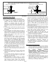
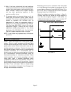
FIGURE 2
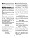
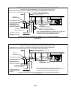
VENT AND AIR INTAKE TERMINATION ON SINGLE WALL VENT
SINGLE WALL TERMINATION
DOUBLE WALL (TYPE B-1) TERMINATION
ROOF FLASHING
ROOF PITCHED
FROM 0" TO 45"
2" CLEARANCE
THIMBLE
SEAL JOINT BETWEEN SINGLE WALL VENT AND “B"
VENT AND THE ANNULAR SPACE OF THE “B" VENT.
CLEARANCE TO BE
AS SPECIFIED ON
TYPE “B" VENT PIPE.
12" MAX
ROOF FLASHING
ROOF PITCHED
FROM 0" TO 45"
SHALL NOT BE A
CONCEALED SPACE
C-Horizontal Venting - General
Common venting is not allowed with horizontal vent.
The minimum horizontal vent length is three feet (914mm).
1- If possible, do not terminate the horizontal vent
through a wall that is exposed to prevailing wind.
Exposure to excessive winds can affect unit
performance. If such a termination is necessary, use a
wind block to protect the vent termination from direct
winds.
2- Vent termination must be free from obstructions and at
least 12" (306mm) above grade level and maximum
snow height.
3- Do not terminate vent directly below roof eaves or
above a walkway, or any other area where condensate
dripping may be troublesome and may cause some
staining. Avoid windows where steam may cause
fogging or ice buildup.
4- When horizontally vented, minimum clearance for
termination from any door, window, gravity air inlet,
gas or electric meter, regulators, and relief equipment
is 4 ft. (1.2m) for U.S. installations. Refer to NFPA
54/ANSI Z223.1 in the U.S.A. and CSA B149.1 and .2
in Canada or with authorities having local jurisdiction.
In Canada, vent termination must have a minimum 6
ft. (1.8mm) horizontal clearance from gas and electric
meters and relief devices as specified in the Canadian
B149.1, Natural Gas Installation Code.
5- Vent termination must be a minimum of 4' (1.2m)
below or 4’ (1.2m) horizontally from any soffit vent or
under-eave vent.
6- Vent must be a minimum of 6' from an inside corner
formed by two exterior walls. If possible, leave a 10'
clearance.
7- Vent termination must be a minimum of 10' (3m) from
any forced air inlet (includes fresh air inlet for other
appliances, such as a dryer).
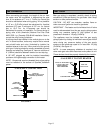
8- When termination is routed through an exterior
combustible wall the vent must be supported using a
listed clearance thimble. Where local authorities
permit, a single section of type B-1 vent pipe may be
used as an alternative to the thimble. When using a
type B-1 vent termination use the clearances specified
by the vent manufacturer. Seal the connection
between the single wall and double wall pipes and the
annular space of the double wall pipe as shown in
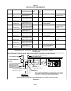
figure 2. Inside edge of vent termination tee or
Belmont cap must be at least 12 inches from outside
wall as shown in figure 3.
9- All horizontal vents must terminate with a tee or with a
cap as specified in table 4. Opening end of tee used
for termination must face downward. Addition of ¼”
(6mm) mesh corrosion resistant material as a bird
screen in the tee or cap openings may be used.
9- For horizontal venting, the vent pipe shall be
supported with hangers no more than 3ft. (1m) apart
to prevent movement after installation.
10- Clearance to combustible material is 6" (152mm) for
single wall vent material except where a listed
clearance thimble is used. Clearance to combustible
material for type B-1 vent or factory-built chimney is
per manufacturer’s instructions. Clearance to
combustible material is 1” at the sides, 1” below, and
3” above on horizontal installations of the concentric
vent/adapter/cap kit
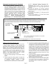
D-Horizontal Venting-Commercial
1- Horizontal commercial installations are for buildings
that are not attached to living spaces. The vent may
be single wall vent material installed according to
the sections Venting A-General
Recommendations and Requirements and C-
Horizontal Venting - General and D-Horizontal
Venting - Commercial. Refer to figures 3, 4, and 5.
The air inlet may be single wall vent material or U.L.
listed single wall flex connector.
2- Refer to table 2 for maximum vent lengths. The vent
pipe diameter for horizontal commercial installations
shall be 3” (76mm) on 45 units, 4” (100mm) on
60/75 units, 5” (127mm)on 100/125 units.