


NOTE: DIAGRAMS & ILLUSTRATIONS NOT TO SCALE.
14
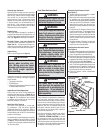
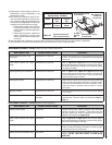
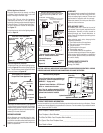
Electronic Appliance Checkout
To light the burner, refer to the lighting instruc-
tions on Pagex 19. Ensure the igniter lights the
pilot. The pilot fl ame should engulf the fl ame
sensor as shown in Figurex 18.
With proper care and maintenance, your appliance
will provide many years of enjoyment. If you should
experience any problem, fi rst refer to the trouble
shooting guide in this manual. If problem persists,
contact your Lennox distributor.
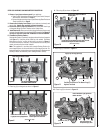
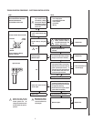
WIRING DIAGRAMS
Wiring diagrams are provided here for refer-
ence purposes only. This information is also
provided on schematics attached directly to the
appliance on a pullout panel located within the
control compartment.
WARRANTY
Your gas appliance is covered by a limited twenty
year warranty. You will fi nd a copy of the war-
ranty accompanying this manual. Please read
the warranty to be familiar with its coverage.
Retain this manual. File it with your other docu-
ments for future reference.
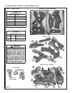
REPLACEMENT PARTS
A complete parts list is found at the end of
this manual. Use only parts supplied from the
manufacturer. Normally, all parts should be
ordered through your Lennox distributor or
dealer. Parts will be shipped at prevailing prices
at time of order.
When ordering repair parts, always give the
following information:
1. The model number of the appliance.
2. The serial number of the appliance.
3. The part number.
4. The description of the part.
5. The quantity required.
6. The installation date of the appliance.
If you encounter any problems or have any ques-
tions concerning the installation or application
of this system, please contact your distributor,
or Lennox directly:
LENNOX HEARTH PRODUCTS
1110 West Taft Avenue
Orange, CA 92865
PRODUCT REFERENCE INFORMATION
We recommend that you record the following important information about your fi replace. Please
contact your Lennox dealer for any questions or concerns. For the number of your nearest Lennox
dealer, please call 800-731-8101
Your Fireplace's Model Number ________________________________________
Your Fireplace's Serial Number ________________________________________
The Date On Which Your Fireplace Was Installed ___________________________
The Type of Gas Your Fireplace Uses ____________________________________
Your Dealer's Name ________________________________________________
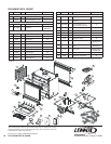
1. If any of the original wire as supplied must be replaced,
1. it must be replaced with Type AWM 105°C – 18 GA.
wire.
2. 120V, 60Hz – Less than 3 amps.
BK
Junction Box
Transf.
120 V.
24 V
BL
Electronic Wiring Diagram (Honeywell)
R
WT
BL
G
W
120
VAC.
BK
W
Gas Valve
B
R
IGNITER
PILOT
ASSEMBLY
BK
G
Outlet Box Green
Ground Screw
Hot side of Outlet
*ON/OFF Switch (Integral
with Gas Valve)
White Wire
To Opposite
Side
*Leave the ON/OFF switch, which is integral
with the gas valve, in the ON position.
SPILL SWITCH
(high limit disc)
WT
G
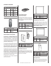
Figure 18
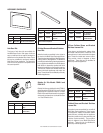
3/8" to 1/2"
(9 -13 mm)
Ground
Electrode
Flame Rod
Hot Surface
Igniter
Proper Flame
Adjustment
Pilot
Nozzels
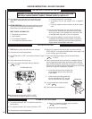
ELECTRONIC PILOT ASSEMBLY
Proper Pilot Flame Appearance
Figure 17
Proper Pilot Flame
Appearance
Thermocouple
Thermopile
Pilot
Nozzels
MILLIVOLT PILOT ASSEMBLY
3/8" Min.
(9 mm)
Igniter Rod
Hood
Figure 20
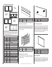
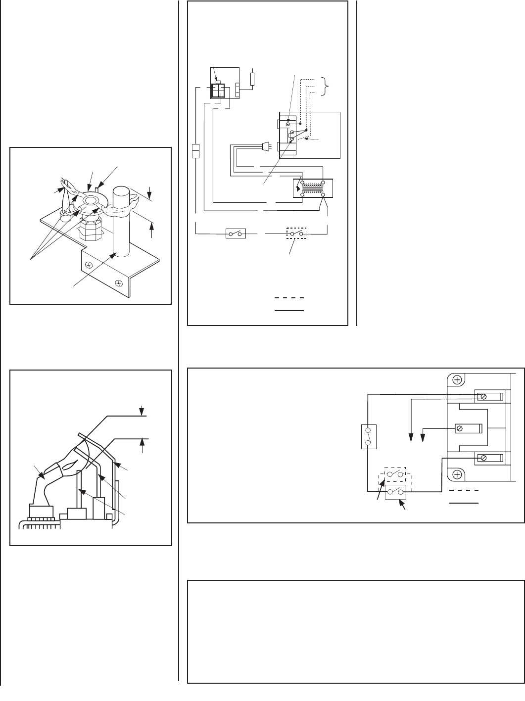
If any of the original wire as supplied must
be replaced, it must be replaced with Type
AWM105 C - 18 gage wire.
* Optional Control Switches - OFF/ON wall
switch or remote control receiver.
Note: Turn the appliance-mounted OFF/ON
burner control switch to the OFF position if an
optional control switch is installed.
Millivolt Wiring Diagram
Figure 19
Thermopile
TH
TP
TH
TP
White
White
Black
Spill Switch
Schematic Represen-
tation Only
Field Wired
Factory
Wired
* Optional Control Switch
Field Wired
Factory
Wired
Schematic Represen-
tation Only
* Optional Control Switches - OFF/ON wall
switch or remote control receiver.
Millivolt Appliance Checkout
The pilot fl ame should be steady, not lifting
or fl oating. Flame should be blue in color with
traces of orange at the outer edge.
The top 3/8" (10 mm) at the pilot generator
(thermopile) and the top ¹⁄₈" min (tip) of the
quick drop out thermocouple should be engulfed
in the pilot fl ame. The fl ame should project 1"
(25 mm) beyond the hood at all three ports.
See Figure 17.
To light the burner, refer to the lighting instruc-
tions on Page 18.
Appliance mounted OFF / ON Switch
CAUTION: LABEL ALL WIRES PRIOR TO DISCONNECTION WHEN SERVICING CONTROLS. WIRING
ERRORS CAN CAUSE IMPROPER AND DANGEROUS APPLIANCE OPERATION.