ADHESIVE-BACKED
FOAMTAPE
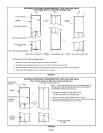
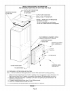
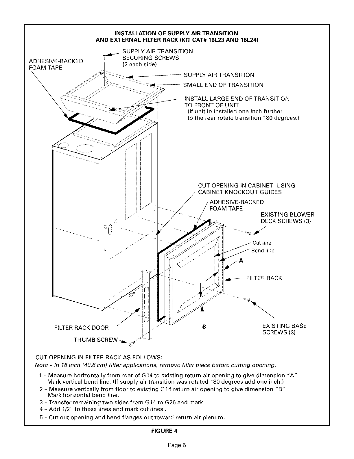
INSTALLATION OF SUPPLY AIR TRANSITION
AND EXTERNAL FILTER RACK (KIT CAT# 161.23 AND 16L24)
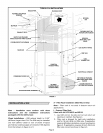
_ SUPPLY AIR TRANSITION
SECURING SCREWS
(2 each side)
SUPPLY AIR TRANSITION
SMALL END OF TRANSITION
INSTALL LARGE END OF TRANSITION
TO FRONT OF UNIT.
(If unit in installed one inch further
to the rear rotate transition 180 degrees.)
ii
FILTER RACK DOOR
THUMB SCREW -_. _;_
CUT OPENING IN CABINET USING
CABINET KNOCKOUT GUIDES
KED
FOAM TAPE
EXISTING BLOWER
DECK SCREWS (3)
FILTER RACK
B
EXISTING BASE
SCREWS (3)
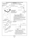
CUT OPENING IN FILTER RACK AS FOLLOWS:
Note - In 16 inch (40.6 cm) filter applications, remove filler piece before cutting opening.
1 - Measure horizontally from rear of G14 to existing return air opening to give dimension "A'.
Mark vertical bend line. (If supply air transition was rotated 180 degrees add one inch.)
2 - Measure vertically from floor to existing G14 return air opening to give dimension "B"
Mark horizontal bend line.
3 - Transfer remaining two sides from G14 to G26 and mark.
4- Add 1/2" to these lines and mark cut lines.
5 - Cut out opening and bend flanges out toward return air plenum.
FIGURE 4
Page 6


