FLEXIBLE ISOLATION
HANGER
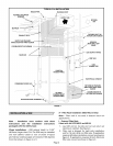
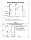
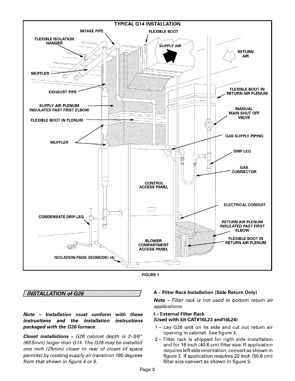
TYPICAL G14 INSTALLATION
FLEXIBLE BOOT
i
/ SUPPLY AIR j ......
J ...... /_ _ RETURN
i i AIR
ii
EXHAUST PIPE
SUPPLY AIR PLENUM
INSULATED PAST FIRST ELBOW
FLEXIBLE BOOT IN PLENUM --
MUFFLER
CONDENSATE DRIP LEG
ISOLATION PADS (ISOMODE) (4) ._
CONTROL
ACCESS PANEL
f-f i i
ii j- ....
i" --- FLEXIBLE BOOT IN
RETURN AIR PLENUM
=
MANUAL
MAIN SHUT OFF
VALVE
GAS SUPPLY PIPING
GP_ ELECTRICAL CONDUIT
............. 0
RETURN AIR PLENUM
INSULATED PAST FIRST
ELBOW
FLEX BLE BOOT N
BLOWER RETURN AIR PLENUM
COMPARTMENT i
ACCESSFANEL !
FIGURE 1
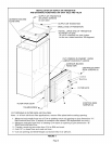
A - Filter Rack Installation (Side Return Only)
Note - Filter rack is not used in bottom return air
applications.
Note - Installation must conform with these
instructions and the installation instructions
I - External Filter Rack
(Used with kit CAT#16L23 and16L24)
packaged with the G26 furnace.
Closet installations - G26 cabinet depth is 2-3/8"
(60.5ram) larger than G14. The G26 may be installed
one inch (25turn) closer to rear of closet (if space
permits) by rotating supply air transition 180 degrees
from that shown in figure 4 or5.
1 - Lay G26 unit on its side and cut out return air
opening in cabinet. See figure 4.
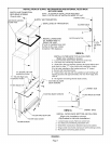
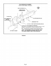
2- Filter rack is shipped for right side installation
and for 16 inch (40.6 cm) filter size. If application
requires left side orientation, convert as shown in
figure 2. If application requires 20 inch (50.8 cm)
filter size convert as shown in figure 3.
Page 3


