


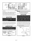
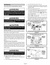
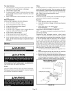
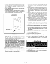
8- Honeywell VR8205 Gas Valve with ON/OFF Switch
- Move gas valve switch to ON. See figure 27.
Honeywell VR8205 Gas Valve with Control Knob -
Turn knob on gas valve counterclockwise _ to ON,
Do not force. See figure 28,
White Rodgers 36G Gas Valve - Move gas valve
switch to ON, See figure 29,
9 - Replace the upper access panel,
10- Turn on all electrical power to to the unit,
11- Set the thermostat to desired setting,
NOTE - When unit is initially started, steps 1 through 11
may need to be repeated to purge air from gas line,
12- If the appliance will not operate, follow the instructions
"Turning Off Gas to Unit" and call your service techni-
cian or gas supplier,
Turning Off Gas to Unit
1 - Set the thermostat to the lowest setting,
2 - Turn off all electrical power to the unit if service is to be
performed,
3 - Remove the upper access panel,
4 - Honeywell VR8205 Gas Valve with ON/OFF Switch
- Move gas valve switch to OFF, See figure 27.
Honeywell VR8205 Gas Valve with Control Knob -
Turn knob on gas valve clockwise clio to OFF, Do not
force, See figure 28,
White Rodgers 36G Gas Valve - Move gas valve
switch to OFF, See figure 29,
5 - Replace the upper access panel.
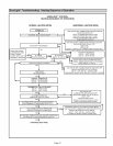
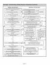
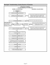
Heating Sequence Of Operation
1 - When thermostat calls for heat, combustion air inducer
starts,
2 - Combustion air pressure switch proves combustion air
inducer operation. Switch is factory set and requires no
adjustment,
3 - After a 15 second prepurge, the hot surface ignitor en-
ergizes,
4- After a 20 second ignitor warm-up period, the gas
valve solenoid opens,
5 - Gas is ignited, flame sensor proves the flame, and the
combustion process continues,
6 - If flame is not detected after first ignition trial, the igni-
tion control will repeat steps 3 and 4 four more times
before locking out the gas valve ("WATCHGUARD"
flame failure mode), The ignition control will then auto-
matically repeat steps 3, 4, 5, and 6 after 60 minutes,
7- To interrupt the 60-minute "WATCHGUARD" period,
move thermostat from "Heat" to "OFF" then back to
"Heat", Heating sequence then restarts at step 1.
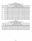
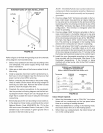
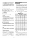
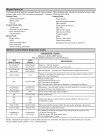
Gas Flow (Approximate)
1 - Operate unit at least 15 minutes before checking gas
flow. Determine the time in seconds for one revolu-
tions of gas through the meter, A portable LP gas me-
ter (17Y44) is available for LP applications,
2 - Compare the number of seconds and the gas meter
size in table 10 to determine the gas flow rate. Multiply
the gas flow rate by the heating value to determine the
unit input rate, If manifold pressure is correct and the
unit input rate is incorrect, check gas orifices for proper
size and restriction,
3 - Remove temporary gas meter if installed,
NOTE - To obtain accurate reading, shut off all other gas
appliances connected to meter,
TABLE 10
Gas Flow Rate (Ft.'_/Hr.)
Seconds for 1
Revolution
10
12
14
16
18
2O
22
24
26
28
3O
32
34
36
38
4O
42
44
46
48
5O
52
54
56
58
6O
Gas Pressure
Gas Meter Size
1/2 cu ft Dial 1 cu ft Dial
180 360
150 300
129 257
113 225
100 200
90 180
82 164
75 150
69 138
64 129
60 120
56 113
53 106
50 100
47 95
45 90
43 86
41 82
39 78
38 75
36 72
35 69
33 67
32 64
31 62
30 60
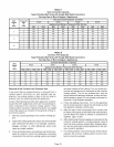
1 - Check the gas line pressure with the unit firing at maxi-
mum rate. A minimum of 4.5 in, w.c. for natural gas or
11,0 in, w,c, for LP/propane gas should be maintained,
2- After the line pressure has been checked and ad-
justed, check the manifold pressure. A natural gas to
LP/propane gas changeover kit is required to convert
the unit, Manifold pressure for all units fueled by natu-
Page 26