


All cementing of joints should be done according to the
specifications outlined in ASTM D 2855.
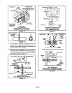
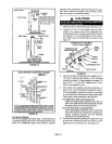
1 - Measure and cut vent pipeto desired length.
2 - Debur and chamfer end of pipe, removing any ddges
or rough edges. If end is not chamfered, edge of pipe
may remove cement fTomfitting socket and result in
a leaking joint.
3 - Clean and dry surfaces to be joined.
4 - Test fit joint and mark depth of fitting on outside of
pipe.
5 - Uniformly applyliberal coat of PVC primer for PVC or
ABS cleaner for ABS to inside socket surface of fit-
ting and male end of pipe to depth of fitting socket.
6 - Promptly apply solvent cement to end of pipeand in-
side socket surface of fitting. Cement should be ap-
plied lightly but uniformly to inside of socket. Take
care to keep excess cement out of socket. Apply
second coat to end of pipe.
NOTE - Time is critical at this stage. Do not allow
pnmer to dry before applying cement.
7 - Immediately after applying last coat of cement to
pipe, and while both inside socketsurface and end of
pipe are wet with cement, forcefully insert endof pipe
into socket until it bottoms out. Turn pipe 1/4 turn dur-
ing assembly (but not after pipe is fully inserted) to
distribute cement evenly.
NOTE - Assembly should be completed within 20
seconds after last application of cement. Hammer
blows should not be used when inse_ng pipe.
8 - After assembly, wipe excess cement from pipe at
end of fitting socket.A properlymadejointwillshowa
bead around itsentire perimeter. Anygaps may indi-
cate a defective assembly due to insufficientsol-
vent.
9 - Handle joints carefully untilcompletelyset.
Iventing ractl es
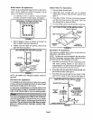
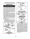
The thickness of construction through which vent!air in-
take pipes may be installed is a minimum of 3 inches (76
mm) and a maximum of 24 inches (610 mm). If a G32 fur-
nace replaces a furnace which was commonly vented
with another gas appliance, the size of the existing vent
pipe for that gas appliance must be checked. Without the
heat of the original furnace flue products, the existingvent
pipe is probably oversized for the single water heater or
other appliance. The vent should be checked for proper
draw with the remaining appliance,
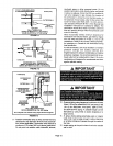
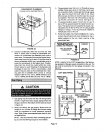
Intake Piping
1 - Cement intakepipinginslip connectorlocated at top
of unit.
2 - Route pipingto outside of structure. Continue with
installationfollowing instructionsgiven in exhaust
and intakepipingterminationsection.
WARNING
Exhaust Piping
1- Cemente_(haustpipthgintofluecollarsocketloceted
on the left side of the top cap.
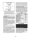
2 - All horizontalrunsofexhaust pipe must slopeback
toward the unit.A minimumof 1/4 inch(6 ram) drop
for each 12inches(305 mm) ofhorizontalrunis man-
datory fordrainage. Horizontal runs ofexhaust pip*
ing must be supported every 5 feet (1.52 m) using
hangers.
Page 9