


Bottom Return Air Applications
If return air is to terminate through the floor under the fur-
nace, a direct, airtight and sealed connection must be
made to the bottom of the furnace,
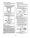
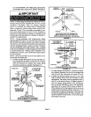
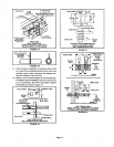
1 - Cut opening in floor or platform. Using knockouts
provided, cut bottom of base panel. See figure 2.
KNOCKOUT PATTERN FOR BOTTOM
RETURN AIR APPLICATION
,v vd
iV Vd
_
FIGURE 2
2 - Bend a flange on return air plenum and lower into
floor or platform opening, See figure 3.
3 - Position unit over return air opening. Seal unit air
tight with return air plenum•
BOTTOM RETURN AIR APPLICATION
G32 UNIT
PROPERLY
SIZED FLOOR
OPENING
RETURN AIR
PLENUM
FIGURE 3
NOTE - Be cerefu/ not to damage insulation. Check for
tight seal,
Side Return Air Applications
For installations where the return air is taken fl'oma retum
airdrop, unitmay be installed with mtum airentl_ through
either the left or rightside of the furnace.
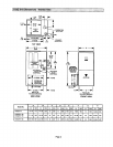
For sidereturnair applications,cutfurnacecabinetat the
dimensionsgiven on page 2. Embossedcomers are pro-
vided onbothcabinet sidesfor returnairopeninglocation.
i_ii_!'2'i:i:i_:"i:ii:i:i:;'i:!:11:71:i:7i:i:7!:;:i!:ii:ii;ii'i:ii'i:_;:""_'::<"_i:":i_i_ii,ii_::i:!Ti:i;_;:7:%TiJ;:::tT;;:::7:7
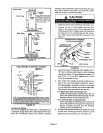
This unit isnot equippedwith a filteror rack.A field-pro-
vided high-velocityfilteris requiredforthe unit tooperate
properly.A filter must be in place any time the unit is
operating. The unit does include filter clips for instal-
lation of a field-provided, internally installed filter.
See figure 4.
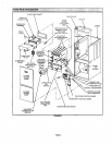
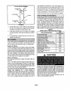
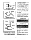
Bottom Return Air Applications
1 - Remove blower access panel.
2- Install filter clips, provided with unit, by slipping
folded section of clip on edge of bottom opening. See
figure 4.
3 - Place filter in bottom of blower compartment beneath
rear filter clip. Press down on filter sides. Filter clips
flex allowing filter to snap into place.
4 - To remove filter, press clip and pull filter up and out.
BOTTOM RETURN FILTER INSTALLATION
REAR FILT R CLIP
URNACE
BACK
SIDE _
FURNACE FURNACE
FIGURE 4
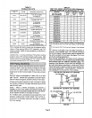
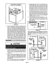
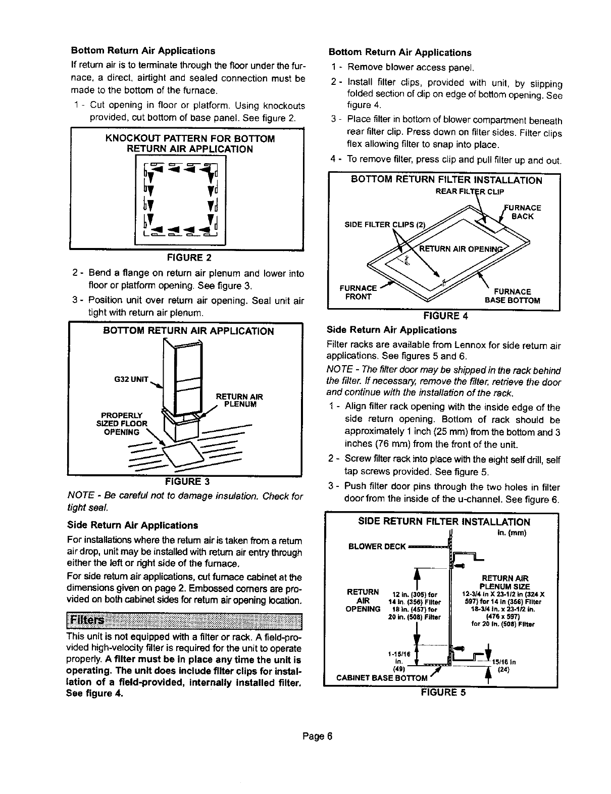
Side Return Air Applications
Filter racks are available from Lennoxfor side returnair
applications.See figures5 and 6.
NOTE - The filter doormay be shipped in the rack behind
the filter./fnecessa_ remove the filter, retrieve the door
and continuewiththe installationof the rack.
1 - Align filter rack opening withthe inside edge of the
side return opening. Bottom of rack should be
approximately1 inch(25 mm) fromthe bottom and 3
inches (76 mm) from the front of the unit.
2 - Screw filter rack intoplacewiththe eightselfddll,self
tap screws provided.See figure 5.
3 - Push filter door pins through the two holes in filter
doorfrom the insideof the u-channel. See figure 6.
SIDE RETURN FILTER INSTALLATION
in.(turn)
BLOWER DECK _=
RETURN 12 in. (305) for
AIR 14 in. 13561Filter
OPENING t8 In. (437) for
20 in, (508) Filter
1-13/t6in.
cAa,NETBASEI; .OM,I
RETURN AIR
PLENUM SIZE
12-314In X 23-1/2 In (324 X
597) for 14 In (356) Filter
18-3/4 In. x 23-1/2 In,
(476 x 507)
for 20 In. 1508) Filter
(34)
FIGURE 5
Page 6