


3- Electrically ground unit in accordance with local
codes or, in the absence of local codes, in accor-
dance with the current National Electric Code (ANSI/
NFPA No. 70) and in Canada with the current Cana-
dian Electric Code part 1 (CSA standard C22.1). The
ground wire is provided in the field make-up box.
To ensure proper grounding of the furnace, two star
washers are included in the electrical make-up box
bag assembly. Place the star washer on secudng
screw before installing the make-up box. Make sure
the star washer breaks the paint on the cabinet so
that the washer is touching metal. Unit is not properly
grounded if paint has not been removed by star
washer.
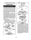
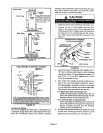
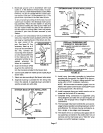
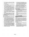
4- An optional 120 volt accessory wira is provided with
G32 units. Install the brown accessory wire into J69
jack plug by inserting the pin of the brown wire into
the open socket of the
jack. See figure 25. Any
accessory rated up to 4
amps can be connected to
this wire. Connect the
neutral leg of the accesso-
ry to the neutral white wire
in the make-up box. The
accessory terminal is en-
ergized whenever the
blower is in operation.
5 - Insert the three-pin (P69)
plug from the control box
INSYALUNG BROWN
ACCESSORY WIRE TO J69
BROWN
WNIT_
NEUTRAL
BLAC
FIGURE 25
into the knockout provided in the blower deck.
6 - Connect jack (J69) from make-up box to jack plug in
blower deck.
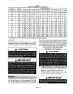
7 - Select wire size according to the blower motor amps.
8 - Snaphole bushing is provided for the widng entry
hole in the cabinet. A snapholeplug is providedto
seal the unused wire entry hole
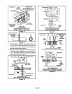
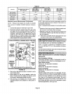
INTERIOR MAKE-UP BOX INSTALLATION
__._ / J69
FIGURE 26
EXTERIOR MAKE-UP BOX INSTALLATION
J69
(Shown with
accesso_
wire connec_d)
P69 from
ControlBox
BUSHING
FIGURE 27
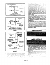
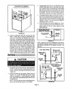
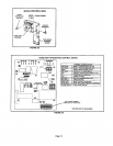
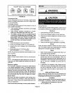
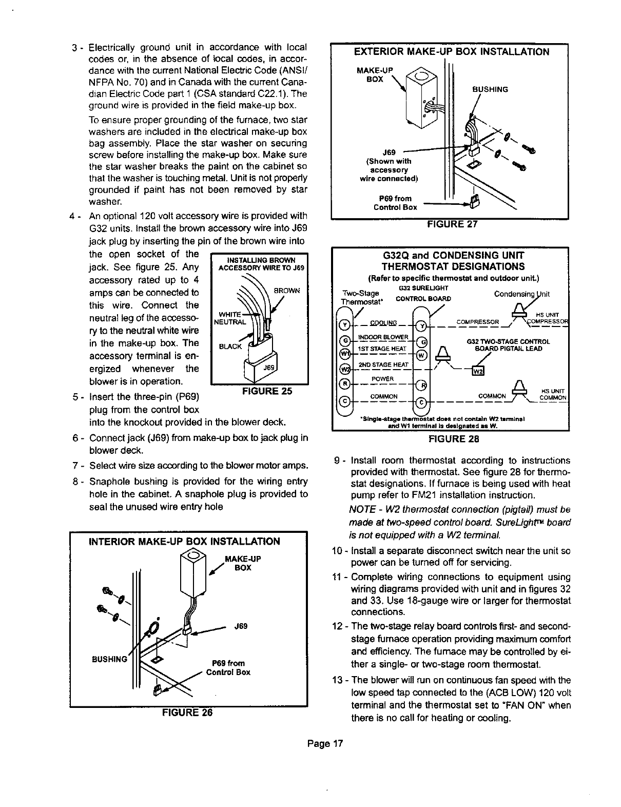
G32Q and CONDENSING UNIT
THERMOSTAT DESIGNATIONS
(Refer to specific thermostat and outdoor unit,)
G32 $UREUGHT
Two-Stage Condensing _nit
Thermostat*/ COkq'ROLBOARD_/ _ _H,sUN,T
J_J=l _G COMPRESSQR OMPRESSC_
® .... ....... ....
(_ J_ -°_"_L°_-_ .(-_ G32"rwo_AGECONTROL
®_ @ co.Mo.A ,so,,T
"$1ngll-_tlge B_s most it don not contain W2 tmrmlnal
and Wl terminal is designated as W.
FIGURE 28
9- Install room thermostat according to instructions
provided with thermostat. See figure 28 for thermo-
stat designations. If furnace isbeing used with heat
pump refer to FM21 installation instruction.
NOTE - W2 thermostat connection (pigtail) must be
made at two-speed control board. SureLight TM board
is not equipped with a W2 terminal
10 - Install a separate disconnect switch near the unit so
power can be turned off for servicing.
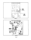
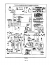
11 - Complete wiring connections to equipment using
wiring diagrams provided with unit and in figures 32
and 33. Use 18-gauge wire or larger for thermostat
connections.
12 - The two-stagerelay board controls first- and second-
stage furnace operation providing maximum comfort
and efficiency. The furnace may be controlled by ei-
ther a single- or two-stage room thermostat.
13 - The blower will run on continuous fan speed with the
low speed tap connected to the (ACB LOW) 120 volt
terminal and the thermostat set to "FAN ON" when
there is no call for heating or cooling.
Page 17