


Page 4
STEP 2 -- REFRIGERANT PIPING -- Flushing Existing Line Set and Indoor Coil
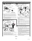
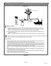
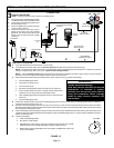
Flush the existing line set per the following
instructions. For more information, refer to the
Installation and Service Procedures manual available
on DaveNet. CAUTION - DO NOT attempt to flush and
re-use existing line sets or indoor coil when the system
contains contaminants (i.e., compressor burn out).
NOTE - When installing refrigerant lines longer than 50 feet,
refer to the Refrigerant Piping Design and Fabrication
Guidelines manual available on DaveNet (Corp. 9351-L9),
or contact the Technical Support Department Product
Application group for assistance.
IMPORTANT !
If this unit is being matched with an approved line set
or indoor unit coil that was previously charged with
mineral oil, or if it is being matched with a coil which
was manufactured before January of 1999, the coil
and line set must be flushed prior to installation. Take
care to empty all existing traps. Polyol ester (POE)
oils are used in Lennox units charged with HFC-410A
refrigerant. Residual mineral oil can act as an insula
tor, preventing proper heat transfer. It can also clog
the expansion device and reduce system perfor
mance and capacity.
Failure to properly flush the system per this instruc
tion and the detailed Installation and Service Proce
dures manual will void the warranty.
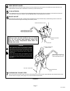
WARNING
When using a high pressure gas such as
nitrogen to pressurize a refrigeration or air
conditioning system, use a regulator that
can control the pressure down to 1 or 2 psig
(6.9 to 13.8 kPa).
WARNING
Refrigerant can be harmful if it is inhaled. Refrigerant
must be used and recovered responsibly.
Failure to follow this warning may result in personal injury
or death.
WARNING
Polyol ester (POE) oils used with HFC-410A
refrigerant absorb moisture very quickly. It is very
important that the refrigerant system be kept closed as
much as possible. DO NOT remove line set caps or
service valve stub caps until you are ready to make
connections.
IMPORTANT !
Some scroll compressors have an internal vacuum
protector that will unload scrolls when suction pres
sure goes below 20 psig. A hissing sound will be
heard when the compressor is running unloaded.
Protector will reset when low pressure in system is
raised above 40 psig. DO NOT REPLACE COMPRES
SOR.
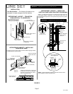
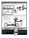
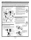
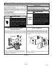
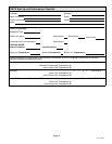
LIQUID LINE FILTER DRIER INSTALLATION
The filter drier (one is shipped with each 13ACX unit) must
be field installed in the liquid line between the outdoor unit's
liquid line service valve and the indoor coil's metering device
(fixed orifice or TXV) as illustrated in figure 6. This filter drier
must be installed to ensure a clean, moisture-free system.
Failure to install the filter drier will void the warranty. A
replacement filter drier is available from Lennox. See
Brazing Connections page 7 for special procedures on
brazing filter drier connections to the liquid line.
OUTDOOR
UNIT
LIQUID LINE
SERVICE VALVE
LIQUID LINE
FILTER DRIER
LINE
LIQUID
LINE
BRAZE CONNECTION POINTS
FIGURE 6
Typical Liquid Line Filter Drier Installation
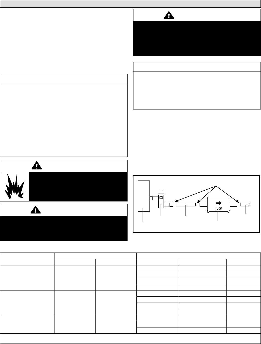
TABLE 2
REFRIGERANT LINE SET — INCHES (MM)
Model Number (-xx*)
Valve Size Connections Recommended Line Sets
Liquid Line Suction Line L15 Line Set Model Line Set Length Catalog Number
13ACX-018-230
13ACX-024-230
3/8” (10 mm) 5/8“ (16 mm)
L15-26-20 20 feet (6.1 m) 89J52
L15-26-25 25 feet (9.1 m) 89J53
L15-26-35 35 feet (12.2 m) 89J54
L15-26-50 50 feet (15.2 m) 89J55
13ACX-030-230
13ACX-036-230
13ACX-042-230
3/8” (10 mm) 3/4” (19 mm)
L15-41-20 20 feet (6.1 m) 89J56
L15-41-30 30 feet (9.1 m) 89J57
L15-41-40 40 feet (12.2 m) 89J58
L15-41-50 50 feet (15.2 m) 89J59
13ACX-048-230
13ACX-060-230
3/8” (10 mm) 7/8” (22 mm)
L15-65-30 30 feet (9.1 m) 89J60
L15-65-40 40 feet (12.2 m) 89J61
L15-65-50 50 feet (15.2 m) 89J62
* Applicable to all minor revision numbers unless otherwise specified.
** Some applications may required a field-provided 1-1/8” to 7/8” adapter.