


Page 11
13ACX SERIES
STEP 4 -- ELECTRICAL -- Circuit Sizing and Wire Routing
In the U.S.A., wiring must conform with current local codes and
the current National Electric Code (NEC). In Canada, wiring
must conform with current local codes and the current
Canadian Electrical Code (CEC).
Refer to the furnace or air handler installation instructions for
additional wiring application diagrams and refer to unit
nameplate for minimum circuit ampacity and maximum
overcurrent protection size.
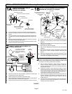
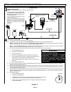
24VAC TRANSFORMER
Use the transformer provided with the furnace or air handler
for low‐voltage control power (24VAC - 40 VA minimum)
WARNING
Electric Shock Hazard. Can cause injury or
death. Unit must be grounded in
accordance with national and local codes.
Line voltage is present at all components
when unit is not in operation on units with
single‐pole contactors. Disconnect all
remote electric power supplies before
opening access panel. Unit may have
multiple power supplies.
IMPORTANT !
If unit is equipped with a crankcase heater, it should
be energized 24 hours before unit start-up to prevent
compressor damage as a result of slugging.
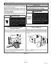
CAUTION
ELECTROSTATIC
DISCHARGE
(ESD)
Precautions and
Procedures
Electrostatic discharge can affect
electronic components. Take care during
unit installation and service to protect the
unit's electronic controls. Precautions will
help to avoid control exposure to
electrostatic discharge by putting the unit,
the control and the technician at the same
electrostatic potential. Touch hand and all
tools on an unpainted unit surface before
performing any service procedure to
neutralize electrostatic charge.
Refer to the unit nameplate for minimum circuit ampacity,
and maximum fuse or circuit breaker (HACR per NEC).
Install power wiring and properly sized disconnect switch.
NOTE — Units are approved for use only with copper
conductors. Ground unit at disconnect switch or
connect to an earth ground.
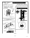
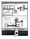
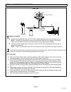
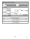
SIZE CIRCUIT AND INSTALL SERVICE
DISCONNECT SWITCH
NOTE — 24VAC, Class II circuit connections are made
in the control panel.
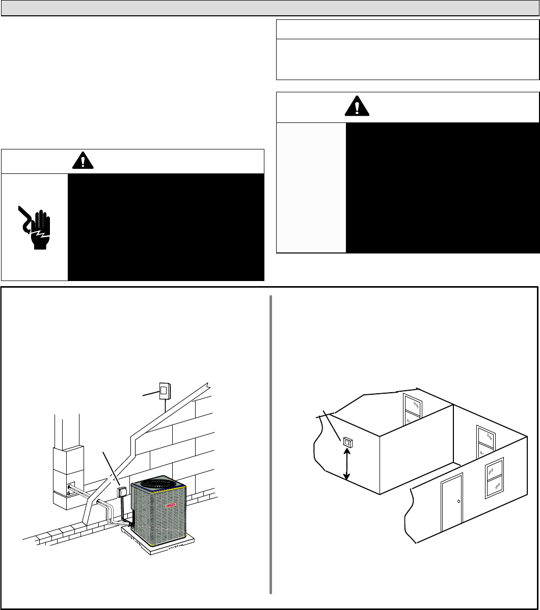
Install room thermostat (ordered separately) on an inside
wall approximately in the center of the conditioned area
and 5 feet (1.5m) from the floor. It should not be installed
on an outside wall or where it can be affected by sunlight
or drafts.
THERMOSTAT
5 FEET
(1.5M)
INSTALL THERMOSTAT
SERVICE
DISCONNECT
SWITCH
MAIN FUSE BOX/
BREAKER PANEL
FIGURE 13