


Page 12
STEP 4 -- ELECTRICAL (CONTINUED) -- High Voltage and Field Control Wiring
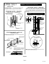
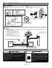
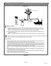
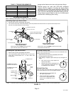
The following illustration provide an example of control wiring connections when using standard thermostat.
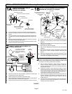
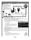
Any excess high voltage field wiring should be
trimmed and secured away from any low voltage field
wiring. To facilitate a conduit, a cutout is located in the
bottom of the control panel. Connect conduit to the
control panel using a proper conduit fitting.
NOTE — Wire tie provides low voltage control wire strain
relief and maintains separation of field-installed low and
high voltage circuits.
NOTE — For proper voltages, select thermostat wire
(control wires) gauge per table above.
NOTE — Do not bundle any excess 24VAC control
wires inside control panel.
Install low voltage wiring from outdoor to indoor unit
and from thermostat to indoor unit as illustrated.
A Run 24VAC control wires through hole with grommet
and secure with provided wire tie.
B Make 24VAC thermostat wire connections. Locate
the two wires from the contactor and make
connection using field-provided wire nuts:
S Yellow to Y1
S Black to C (common)
ROUTING HIGH VOLTAGE, GROUND AND CONTROL WIRING
WIRE RUN LENGTH AWG# INSULATION TYPE
LESS THAN 100' (30 METERS) 18 TEMPERATURE RATING
MORE THAN 100' (30 METERS) 16 35ºC MINIMUM.
HIGH VOLTAGE / GROUND WIRES
FIELD CONTROL WIRING
W1
Y
G
C
R
Y
G
C
THERMOSTAT INDOOR UNIT
POWER
HEAT
COOLING
INDOOR BLOWER
COMMON
OUTDOOR UNIT
Y1
C
W
R
YELLOW
BLACK
FIGURE 14
STEP 5 -- UNIT START-UP
IMPORTANT
If unit is equipped with a crankcase heater, it should be
energized 24 hours before unit start-up to prevent
compressor damage as a result of slugging.
1. Rotate fan to check for binding.
2. Inspect all factory- and field-installed wiring for loose
connections.
3. After evacuation is complete, open the liquid line and
suction line service valve stems to release the
refrigerant charge (contained in outdoor unit) into the
system.
4. Replace the stem caps and tighten to the value listed in
table 3.
5. Check voltage supply at the disconnect switch. The
voltage must be within the range listed on the unit's
nameplate. If not, do not start the equipment until you
have consulted with the power company and the voltage
condition has been corrected.
6. Connect manifold gauge set for testing and charging
using figure NO TAG as a guideline.
7. Set the thermostat for a cooling demand. Turn on power
to the indoor indoor unit and close the outdoor unit
disconnect switch to start the unit.
8. Recheck voltage while the unit is running. Power must
be within range shown on the unit nameplate.
9. Check system for sufficient refrigerate using the
procedures outlined in under System Refrigerant.
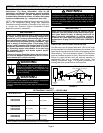
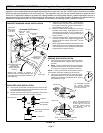
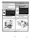
OPERATING MANIFOLD GAUGE SET AND SERVICE
VALVES
The liquid and vapor line service valves are used for
removing refrigerant, flushing, leak testing, evacuating,
checking charge and charging.
Each valve is equipped with a service port which has a
factory-installed valve stem. Figure 15 provides information
on how to access and operating both angle and ball service
valves.
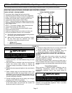
Torque Requirements
When servicing or repairing heating, ventilating, and air
conditioning components, ensure the fasteners are
appropriately tightened. Table 3 lists torque values for
fasteners.
IMPORTANT
To prevent stripping of the various caps used, the
appropriately sized wrench should be used and fitted
snugly over the cap before tightening.
When servicing or repairing HVAC components, ensure the
fasteners are appropriately tightened. Table 3 provides
torque values for fasteners.