


Page 21
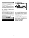
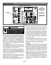
System Operation Monitor (LSOM)
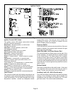
The system operation monitor (A132) detects the most
common fault conditions in the air conditioning system.
When an abnormal condition is detected, the module
communicates the specific condition through its ALERT
and TRIP lights. The module is capable of detecting both
mechanical and electrical system problems. See figure 15
for the system operation monitor.
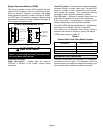
System Operation Monitor (A132)
DATA OUTPUT
CONNECTOR
.25" SPADE
CONNECTOR
POWER LED
DATA OUTPUT
Y
C
ALERT LED
TRIP LED
Figure 15
IMPORTANT
This monitor does not provide safety protection. The
monitor is a monitoring device only and cannot con-
trol or shut down other devices.
LSOM LED Functions
Power LED (green) −− Voltage within the range of
19−28VAC is present at the system monitor power
connection.
Alert LED (yellow) −− Communicates an abnormal system
condition through a unique flash code. The alert LED
flashes a number of times consecutively; then pauses;
then repeats the process. This consecutive flashing
corresponds with a particular abnormal condition.
Trip LED (red) −− Indicates a demand signal from the
thermostat; but detects no current to the compressor.
Flash code number −− Corresponds to a number of LED
flashes, followed by a pause, and then repeated.
Trip & Alert LEDs flashing simultaneously −− Indicates that
the control circuit voltage is too low for operation.
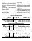
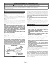
The monitor has an automatic reset function which is
based on the number of normal run cycles. See table 9.
LSOM codes are given in table 10.
Table 9
Comfort Alert Code Auto−Reset Function
Code Number
Normal Run Cycles Required
for Automatic Reset
1 30
2, 3, 4 4
5, 6, 7, 9 1
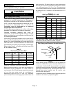
Condenser Fan Clearances
The top of the condenser fan should be 1−1/2 inches from
the bottom of the top grille. This dimension should be
checked and the fan should be adjusted accordingly any
time servicing of the outdoor fan system is required.