


Page 12
Electrical
All wiring should be done in accordance with the
current National Electric Code ANSI/NFPA No. 70 in the
United States. In Canada, wiring must be done in
accordance with the current CSA C22.2 Part 1. Local
codes may take precedence.
Use wiring with a temperature limitation of 75_C min.; run
the 208 or 230 volt, 60 hertz electric power supply through a
fused disconnect switch to control box of unit and connect
as shown in the wiring diagram located on the inside of the
control access panel.
Unit must be electrically grounded in accordance with local
codes or in the absence of local codes with the National
Electric Code, ANSI/NFPA No. 70 (latest edition) or CSA
C22.2 Part 1 (latest edition).
Power supply to the unit must be N.E.C. Class 1, and must
comply with all applicable codes. A fused disconnect
switch should be field provided for the unit. The switch must
be separate from all other circuits. If any of the wire
supplied with the unit must be replaced, replacement wire
must be of the type shown on the wiring diagram.
Electrical wiring must be sized to carry minimum circuit
ampacity marked on the unit. USE COPPER
CONDUCTORS ONLY. Each unit must be wired with a
separate branch circuit and be properly fused.
CAUTION
When connecting electrical power and control wir-
ing to the unit, waterproof type connectors MUST be
used so that water or moisture cannot be drawn into
the unit during normal operation.
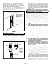
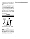
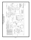
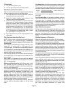
See figure 10 for field connection of line voltage wiring. See
figure 11 for typical wiring diagram.
208/230 Line Voltage Wiring
NOTE − If 208 voltage is supplied, transformer
connections must be made.
L1
ground
lug
L2
Figure 10
contactor
fused disconnect switch
(furnished by installer)
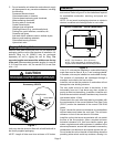
Thermostat
The room thermostat should be located on an inside wall
where it will not be subject to drafts, sun exposure or heat
from electrical fixtures or appliances. Follow
manufacturer’s instructions enclosed with thermostat for
general installation procedure. Color coded insulated wires
(# 18 AWG) should be used to connect thermostat to unit.
Four wires are required for cooling.
Heat Anticipator Setting
It is important that the anticipator setpoint be correct. Too
high of a setting will result in longer heat cycles and a
greater temperature swing in the conditioned space.
Reducing the value below the correct setpoint will give
shorter ON" cycles and may result in the lowering of the
temperature within the conditioned space.
Heat Anticipator Setting: 0.70 AMP