


Page 11
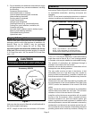
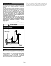
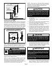
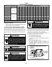
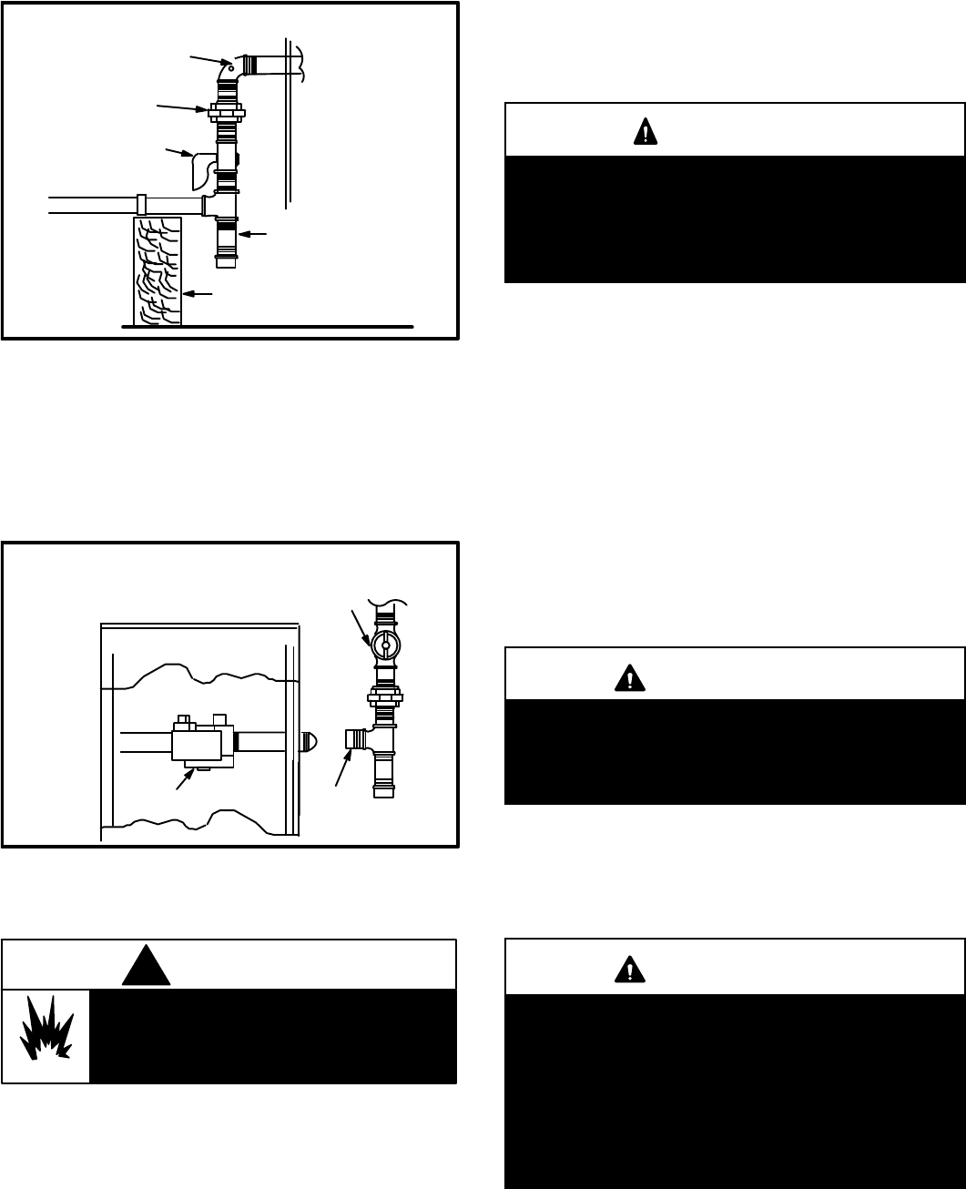
Figure 8
unit
ground joint
union
field provided
1/8 in. pressure tap
manual main
shut−off valve
drip
leg
gas piping
support
Drip Leg Installation
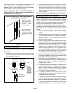
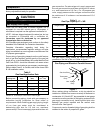
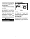
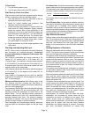
Pressure Test Gas Piping
When pressure testing gas lines, the gas valve must be
disconnected and isolated. Gas valve can be damaged if
subjected to more than 0.5 psig (14 inch w.c.). See figure 9.
If test pressure is equal to or less than 0.5 psig (14 inch
w.c.) shutoff the manual main shut-off valve before
pressure testing to isolate unit from gas supply system.
gas valve
cap
Manual Main Shut−off Valve Will Not Hold Test
Pressures in Excess of 0.5 PSIG (14 in. w.c.)
Figure 9
unit
Isolate Gas Valve To Pressure Test
NOTE − Codes may require that manual main shut off valve
and union (furnished by installer) be installed in gas line
external to unit. Union must be of the ground joint type.
Danger of explosion. Can cause injury or
product or property damage. Do not use
matches, candles, flame or other sources
of ignition to check for leaks.
WARNING
!
After gas piping is complete, carefully check all piping
connections (factory and field) for gas leaks. Use soap
solution or other preferred means.
NOTE − In case of emergency shutdown, shut off main
manual gas valve and disconnect main power to unit.
These devices should be properly labeled by installer.
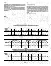
The heating value of the gas may differ with locality. The
value should be checked with the local gas utility.
NOTE − There may be a local gas utility requirement
specifying a minimum diameter for gas piping. All units
require a 1/2 inch pipe connection at the gas valve.
Gas piping recommendations:
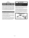
CAUTION
If a flexible gas connector is required or allowed by
the authority that has jurisdiction, black iron pipe
shall be installed at the gas valve and must extend
outside the cabinet. The flexible connector can then
be added between the black iron pipe and the gas
supply line.
1 − A drip leg and a ground joint union must be installed in
the gas piping.
A ground joint union is recommended by the
manifold/valve.
2 − When required by local codes, a manual shut-off valve
may have to be installed outside of the unit.
3 − Use pipe thread sealing compound resistant to
propane gas sparingly on male threads.
4 − The gas supply should be a separate line and installed
in accordance with all safety codes. After the gas
connections have been completed, open the main
shut-off valve admitting normal gas pressure to the
mains. Check all joints for leaks with soap solution or
other material suitable for the purpose.
CAUTION
Some soaps used for leak detection are corrosive to
certain metals. Carefully rinse piping thoroughly af-
ter leak test has been completed. Do not use
matches, candles, flame or other sources of ignition
to check for gas leaks.
5 − The unit and its individual manual shut-off valve must
be disconnected from the gas supply piping system
during any pressure testing of that system at test
pressures in excess of 1/2 PSIG (3.48kPa).
IMPORTANT
The unit must be isolated from the gas supply piping
system by closing its individual manual shut−off
valve during any pressure testing of the gas supply
piping system at test pressures equal to or less than
1/2 psig. See figure 9.
The unit and its individual shut−off valve must be dis-
connected from the gas supply piping system during
any pressure testing of the system at test pressures
greater than 1/2 psig.
6 − A 1/8 inch N.P.T. plugged tapping, accessible for test
gage connections, must be installed immediately
upstream of the gas supply connection to the furnace.