


Page 7
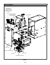
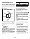
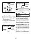
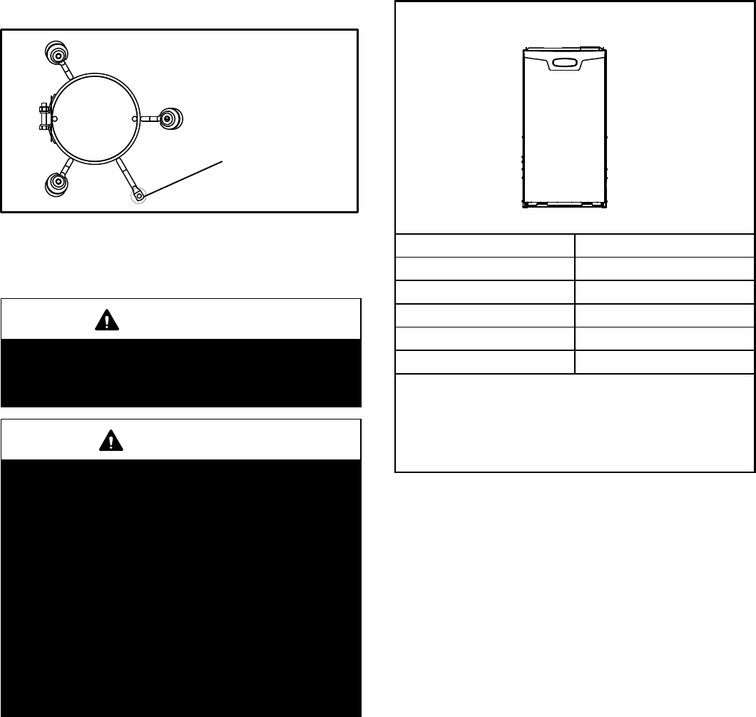
NOTE − The 1/2 hp blower motor used in some SLP98DFV
unit is equipped with three flexible legs and one rigid leg.
The rigid leg is equipped with a shipping bolt and a flat white
plastic washer (rather than the rubber mounting grommet
used with a flexible mounting leg). The bolt and washer
must be removed before the furnace is placed into op-
eration. After the bolt and washer have been removed, the
rigid leg will not touch the blower housing.
FIGURE 6
RIGID LEG
remove shipping bolt and washer
SLP98DF070V36B and
SL98DF090V036C WITH 1/2 HP
BLOWER MOTOR
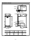
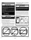
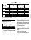
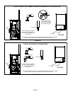
Allow for clearances to combustible materials as indicated
on the unit nameplate. Minimum clearances for closet or al-
cove installations are shown in figure 7.
WARNING
Blower access panel must be securely in place when
blower and burners are operating. Gas fumes, which
could contain carbon monoxide, can be drawn into
living space resulting in personal injury or death.
WARNING
Improper installation of the furnace can result in per-
sonal injury or death. Combustion and flue products
must never be allowed to enter the return air system
or air in the living space. Use sheet metal screws and
joint tape to seal return air system to furnace.
In platform installations with furnace return, the fur-
nace should be sealed airtight to the return air ple-
num. A door must never be used as a portion of the
return air duct system. The base must provide a
stable support and an airtight seal to the furnace. Al-
low absolutely no sagging, cracks, gaps, etc.
For no reason should return and supply air duct sys-
tems ever be connected to or from other heating de-
vices such as a fireplace or stove, etc. Fire, explo-
sion, carbon monoxide poisoning, personal injury
and/or property damage could result.
The unit may be installed three ways in downflow applica-
tions: on non−combustible flooring, on combustible flooring
using a base, or on a reverse−flow cooling coil cabinet. Do
not drag the unit across the floor in the downflow posi-
tion. Floor and flange damage will result.
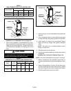
Refer to figure 7 for clearances in downflow applica-
tions.
Downflow Application Installation Clearances
Top
Bottom
Left Side Right Side
Top 0
*Front 0
Back 0
Sides 0†
Vent 0
Floor NC‡
*Front clearance in alcove installation must be 24 in. (610 mm).
Maintain a minimum of 24 in. (610 mm) for front service access.
†Allow proper clearances to accommodate condensate trap and
vent pipe installation.
‡The furnace may be installed on a combustible wood floor if an op-
tional base is installed between the furnace and the combustible
floor.
FIGURE 7
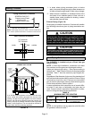
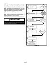
Installation on Non−Combustible Flooring (Figure 8)
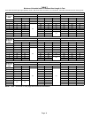
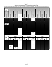
1 − Cut floor opening keeping in mind clearances listed on
unit rating plate. Also keep in mind gas supply connec-
tions, electrical supply, flue and air intake connections
and sufficient installation and servicing clearances.
See table 1 for correct floor opening size.
2 − Flange warm air plenum and lower the plenum into the
opening.
3 − Set the unit over the plenum and seal the plenum to
the unit.
4 − Ensure that the seal is adequate.