


Page 25
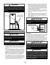
CAUTION
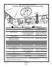
A separate drain line must be run to the drain from
the condensate trap to ensure proper drainage and
pressure switch operation. DO NOT connect the con-
densate trap drain into the drain line from the evapo-
rator coil.
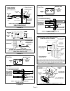
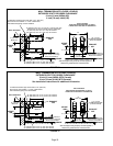
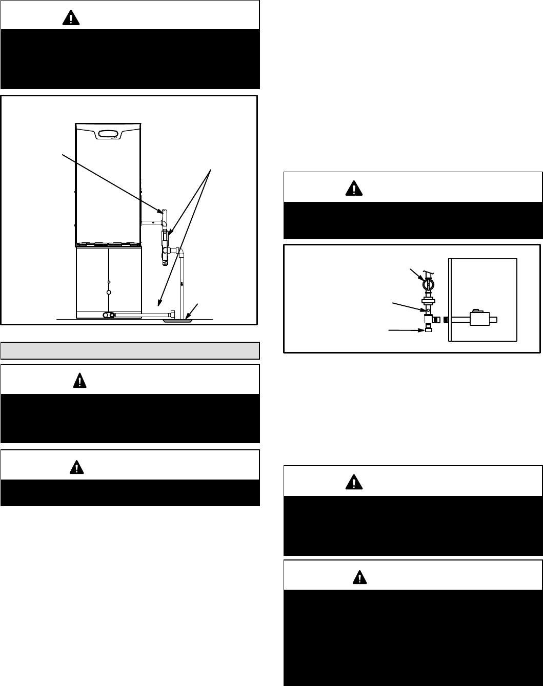
FIGURE 35
SL98DFV with Evaporator Coil
Drain
Condensate trap and
evaporator coil must drain
separately as shown.
Field−Provided Vent
Gas Piping
CAUTION
If a flexible gas connector is required or allowed by
the authority that has jurisdiction, black iron pipe
shall be installed at the gas valve and extend outside
the furnace cabinet.
WARNING
Do not exceed 600 in−lbs (50 ft.−lbs) torque when at-
taching the gas piping to the gas valve.
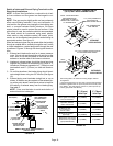
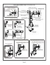
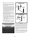
1 − Gas piping may be routed into the unit through either
the left- or right-hand side. Supply piping enters into
the gas valve from the side of the valve as shown in
figure 37.
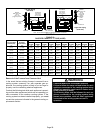
2 − When connecting gas supply, factors such as length of
run, number of fittings and furnace rating must be con-
sidered to avoid excessive pressure drop. Table 10
lists recommended pipe sizes for typical applications.
NOTE − Use two wrenches when connecting gas pip-
ing to avoid transferring torque to the manifold.
3 − Gas piping must not run in or through air ducts, clothes
chutes, chimneys or gas vents, dumb waiters or eleva-
tor shafts. Center gas line through piping hole. Gas
line should not touch side of unit. See figure 37.
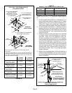
4 − Piping should be sloped 1/4 inch per 15 feet (6mm per
5.6m) upward toward the gas meter from the furnace.
The piping must be supported at proper intervals, ev-
ery 8 to 10 feet (2.44 to 3.05m), using suitable hangers
or straps. Install a drip leg in vertical pipe runs to serve as
a trap for sediment or condensate.
5 − A 1/8" N.P.T. plugged tap or pressure post is located on
the gas valve to facilitate test gauge connection. See
figures 45.
6 − In some localities, codes may require installation of a
manual main shut-off valve and union (furnished by in-
staller) external to the unit. Union must be of the
ground joint type.
IMPORTANT
Compounds used on threaded joints of gas piping
must be resistant to the actions of liquified petro-
leum gases.
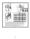
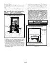
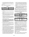
FIGURE 36
MANUAL MAIN SHUT−OFF
VALVE WILL NOT HOLD
NORMAL TEST PRESSURE
CAP
FURNACE
ISOLATE
GAS VALVE
1/8" N.P.T.
PLUGGED
TAP
Leak Check
After gas piping is completed, carefully check all piping
connections (factory− and field−installed) for gas leaks. Use
a leak detecting solution or other preferred means.
The furnace must be isolated from the gas supply system
by closing its individual manual shut-off valve during any
pressure testing of the gas supply system at pressures less
than or equal to 1/2 psig (3.48 kPa, 14 inches w.c.).
IMPORTANT
When testing gas lines using pressures in excess of
1/2 psig (3.48 kPa), gas valve must be disconnected
and isolated. See figure 36. Gas valves can be dam-
aged if subjected to pressures greater than 1/2 psig
(3.48 kPa).
WARNING
FIRE OR EXPLOSION HAZARD
Failure to follow the safety warnings exactly could
result in serious injury, death, or property damage.
Never use an open flame to test for gas leaks. Check
all connections using a commercially available soap
solution made specifically for leak detection. Some
soaps used for leak detection are corrosive to certain
metals. Carefully rinse piping thoroughly after leak
test has been completed.