


Page 12
Venting Practices
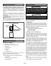
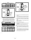
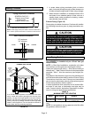
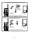
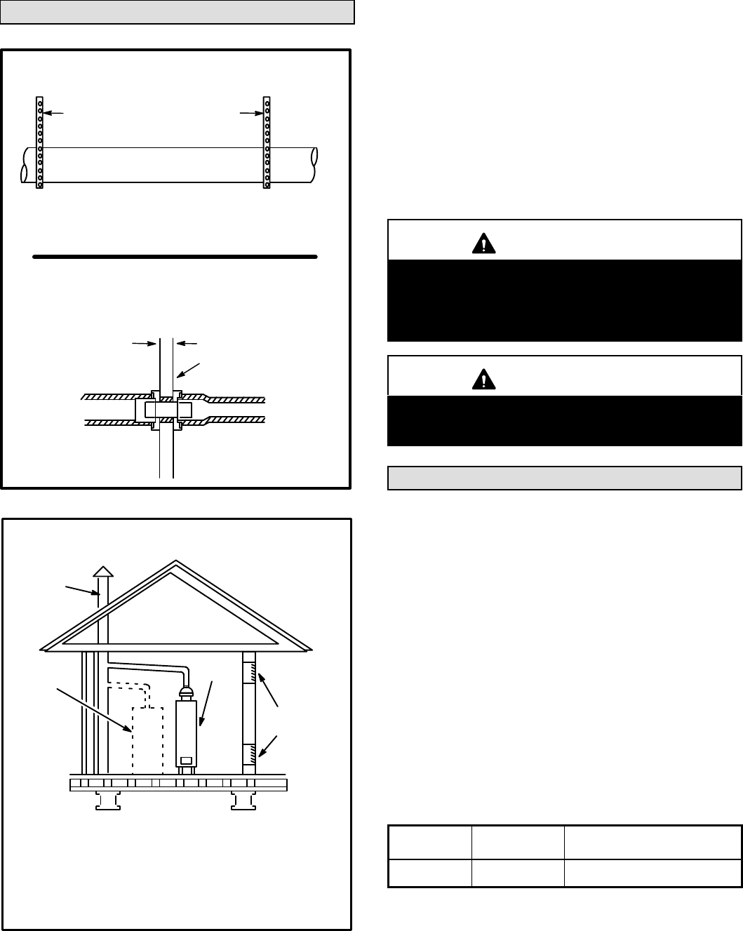
FIGURE 13
* See table 4 for allowable pipe.
Piping Suspension Guidelines
NOTE − Isolate piping at the point where it exits the outside wall or
roof in order to prevent transmission of vibration to the structure.
SCHEDULE 40 PVC −−
Support every 5 feet.
all other pipe* −−
Support every 3 feet.
Wall
inside outside
24" maximum
3/4" minimum
Wall Thickness Guidelines
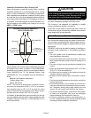
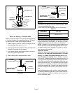
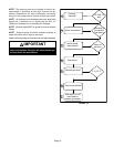
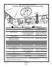
REPLACING FURNACE THAT WAS PART OF A
COMMON VENT SYSTEM
CHIMNEY
OR GAS
VENT
(Check sizing
for water
heater only)
FURNACE
(Replaced
by SLP98)
WATER
HEATER
OPENINGS
(To Adjacent
Room)
If an SLP98 furnace replaces a furnace which was com-
monly vented with another gas appliance, the size of the
existing vent pipe for that gas appliance must be checked.
Without the heat of the original furnace flue products, the
existing vent pipe is probably oversized for the single water
heater or other appliance. The vent should be checked for
proper draw with the remaining appliance.
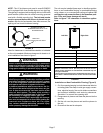
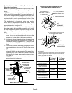
FIGURE 14
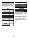
1 − In areas where piping penetrates joists or interior
walls, hole must be large enough to allow clearance on
all sides of pipe through center of hole using a hanger.
2 − When furnace is installed in a residence where unit is
shut down for an extended period of time, such as a
vacation home, make provisions for draining conden-
sate collection trap and lines.
Exhaust Piping (Figure 16)
Route piping to outside of structure. Continue with installa-
tion following instructions given in piping termination sec-
tion.
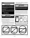
CAUTION
Do not discharge exhaust into an existing stack or
stack that also serves another gas appliance. If verti-
cal discharge through an existing unused stack is re-
quired, insert PVC pipe inside the stack until the end
is even with the top or outlet end of the metal stack.
CAUTION
The exhaust vent pipe operates under positive pres-
sure and must be completely sealed to prevent leak-
age of combustion products into the living space.
Vent Piping Guidelines
The SLP98DFV is installed only as a Direct Vent gas
central furnace.
NOTE − In Direct Vent installations, combustion air is taken
from outdoors and flue gases are discharged outdoors.
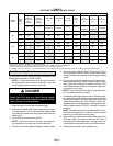
Intake and exhaust pipe sizing −− Size pipe according to
tables 6 and 7. Table 6 lists the minimum vent pipe lengths
permitted. Table 7 lists the maximum pipe lengths per-
mitted.
Regardless of the diameter of pipe used, the standard roof
and wall terminations described in section Exhaust Piping
Terminations should be used. Exhaust vent termination
pipe is sized to optimize the velocity of the exhaust gas as
it exits the termination. Refer to table 9.
In some applications which permit the use of several differ-
ent sizes of vent pipe, a combination vent pipe may be
used. Contact Lennox’ Application Department for assis-
tance in sizing vent pipe in these applications.
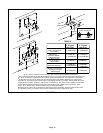
TABLE 6
MINIMUM VENT PIPE LENGTHS
SLP98DF
MODEL
MIN. EQUIV.
VENT LENGTH
EXAMPLE
070, 090, 110
15 ft.*
5 ft. plus 2 elbows of 2", 2−1/2"
or 3" diameter pipe
*Any approved termination may be added to the minimum equivalent length
listed.
NOTE − It is acceptable to use any pipe size which fits within
the guidelines allowed in table 7.