


Page 8
EDA 01/06
Leak Testing, Evacuating, Charging
IMPORTANT
The 3−way diverting valve actuator shaft setscrew
(see figure 7) is factory set and is not to be adjusted.
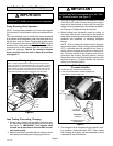
3−way Diverting Valve Operation
NOTE − During system operation, the 3-way valve requires
24-volt power to drive between cooling and dehumidifica-
tion.
The 3−way diverting valve is actually two valves connected
by a common shaft, designed to open one valve while clos-
ing the other, and vice versa. For evacuating (with power
off), the diverting valve can be REPOSITIONED using its
actuator lever, a long setscrew that has been factory-set to
a precise point on the common shaft. Do not loosen (un-
screw) the setscrew. Should the setscrew become
loose, carefully follow the note in figure 6 to position
and tighten it.
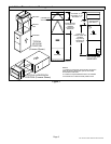
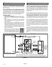
Re−aligning Setscrew
Figure 6
NOTE − Actuator shaft setscrew is factory set and must not be ad-
justed. If the set screw should become loose, use a pliers to grip the
shaft where shown (1) and rotate the shaft (in direction of the black
arrow) until the pin stops (inset shows pin and stops). Press the red
button (2) in the direction of the white arrow and move the lever (3)
to the forward position and tighten setscrew to 60 in-lbs torque.
STOP
PIN
SHAFT
STOP
2
3
1
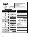
Leak Testing, Evacuating, Charging
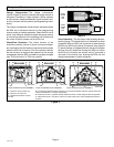
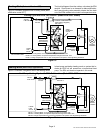
1. Set the 3−way diverting valve actuator shaft to the cen-
ter (evacuate) position for leak testing and evacuation
(see figure 7). IMPORTANT! The actuator shaft
must be set as described to allow the EDA to evac-
uate more quickly.
2. Refer to instructions provided with the outdoor unit for
leak testing, evacuating and charging procedures.
IMPORTANT
Prior to starting the outdoor unit for charging, be
sure the 3-way valve is energized and in the cool-
ing" (forward) position (see figure 7).
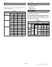
3. Very little charge is required for the additional volume
of the EDA unit. When in normal cooling, the compo-
nents will all be occupied by vapor that has very little
weight. At most (depending on the model) an addition-
al 1/4 pound of refrigerant may be required.
4. When shifting from dehumidify mode to cooling, or
vice versa, wait at least 10 minutes for the system to
reach stable operating pressure before checking tem-
peratures and pressures, or adjusting refrigerant
charge.
NOTE − Prior to starting the outdoor unit for charging,
set the thermostat to call for cooling (dehumidification
OFF). It will take about 90 seconds for the 3−way di-
verting valve to energize and shift to the cooling posi-
tion. To ensure that the 3-way diverting valve is ener-
gized and in the cooling" (forward) position, observe
the position of the 3-way diverting valve actuator shaft
setscrew in figure 7; if properly shifted, the setscrew
will be in the forward position.
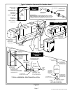
1
2
Setting 3−Way Diverting Valve to
Evacuate Position
Figure 7
COOLING
(FORWARD)
EVACUATE
(CENTER)
DEHUMIDIFICATION
(REARWARD)
1. PUSH RED TAB IN DIRECTION INDICATED.
2. PUSH ACTUATOR SHAFT DOWN TOWARD THE
CENTER−OF−TRAVEL POSITION
5. The charge must be checked with the system in cool-
ing operation (dehumidification OFF). After testing
and charging as required, set the thermostat to force
a demand for dehumidification.