


Page 13
EDA INSTALLATION/ SERVICE INSTRUCTIONS
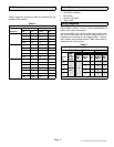
Air Resistance
Table 2 shows air volume and total air resistance for the
available EDA models.
Table 2
Air Resistance
Air Volume Total Air Resistance
Model No.
cfm L/s in. w.g. Pa
EDA−024B
400 190 0.05 12
600 285 0.10 25
800 380 0.15 37
1000 470 0.22 55
EDA−036C
600 285 0.05 12
800 380 0.08 20
1000 470 0.11 27
1200 565 0.15 37
1400 660 0.20 50
EDA−060DB
1000 470 0.05 12
1200 565 0.06 15
1400 660 0.08 20
1600 755 0.10 25
1800 850 0.11 27
2000 945 0.13 32
2200 1040 0.15 37
Repair Parts
S 3−way diverting valve assembly
S Check/flow restrictor
S EDA Relay
S Outdoor unit relay
S Teflon seals
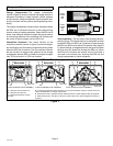
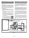
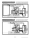
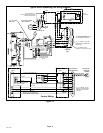
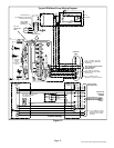
Wiring Diagrams
Typical condensing unit and heat pump wiring diagrams
are provided in figures 12 and 13. Some modifications to
certain units may be necessary.
Connect the EDA unit with the indoor and outdoor units,
and to the thermostat. Be sure the outdoor sensor is
installed and connected to the SignatureStatt thermo-
stat’s outdoor sensor terminal block. Table 3 shows the re-
quirements for control wiring.
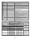
Table 3
Control Wiring Requirements
Units: (all) (with LSOM) (without LSOM)
Signa-
Indoor unit to:
System
type
Si
gna-
tureS-
tatt to
Sensor
Humidi-
trol®
EDA
Signatu-
reStatt
Out-
door
unit
Signatu-
reStatt
Out-
door
unit
2 stage
AC
9* 6 8* 4
1 stage
AC
2
(twisted
3
8* 5 7* 3
2 stage
HP
(t
w
i
s
t
e
d
pair)
3
10* 8 9* 7
1 stage
HP
9* 7 8* 6
*Includes conductor for 2−stage heat