


Page 12
EDA 01/06
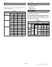
Check List
n Checkpoint What to Check Action
Thermostat and
Sensor
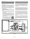
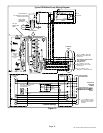
Wiring Confirm Sensor connected to SignatureStatt using twisted pair
wire (see wiring diagram figure 13)
Thermostat Humiditrol
®
Installer Settings Confirm HUMIDITROL is enabled (see figure 8)
Thermostat Humiditrol
®
User Settings Confirm HUMIDITROL − Dehumidify − ON is selected (see figure 8)
Thermostat Humiditrol
®
User Settings Confirm Relative Humidity setting (see figure 8)
Indoor Unit Variable-Speed Blower Settings Confirm Settings for D": CFM = 60% to 65% of 2nd-stage cool
(see indoor unit installation instructions and table 1, below)
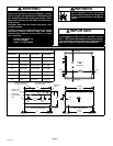
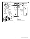
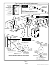
Insulation Charge Compensator
C fi i l ti i l i t ll d ( h t kit
Insulation Liquid Line
Confirm insulation is properly installed (see charge compensator kit
instructions; also, see figure 5)
Insulation Vent Line to Suction Line
instructions;
also
,
see
figure
5)
Charge Compen-
sator
1/4"Line Confirm 1/4" port oriented downward (see charge compensator
details, figure 5)
Check/Flow Re-
strictor
3/8" Line Confirm restrictor installed/oriented properly (see check/flow restric-
tor details figure 5)
System Charge Refrigerant With unit running in cooling mode, check and confirm system is
properly charged (see outdoor unit installation instructions).
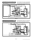
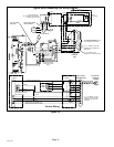
Outdoor Unit Fan Relay Confirm (if unit has variable speed outdoor fan) relay is installed
properly (see wiring diagram figures 12 and 13)
Outdoor Unit EDA Label Confirm label is installed in prominent location and will be easily
visible during servicing.
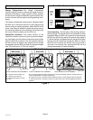
NOTE − System will NOT operate in dehumidification mode with outdoor temperature at or above 95ºF.
Operational Status Dehumidification Mode Record supply air temperature and confirm temperature that it is
higher than in cooling mode.
Operational Status Dehumidification Mode On units with variable speed outdoor fan, check that fan operates
at approximately 250 rpm (lowest speed).
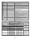
Table 1
Demand Signals − Humiditrol
®
EDA Enabled
Operating Sequence System Demand System Response
Thermostat Demand Relative Humidity
Com
Blower
CFM
System Type Step
Y1 Y2 O G Status D
Com-
pressor
CFM
(Cool) %
Comments
Cooling Operation − No call for dehumidification
Single-stage outdoor unit 1 ON (na) ON ON Acceptable 24 VAC High 100
Compressor and indoor
bl f ll th t t
Two-stage outdoor unit Y1 1 ON − ON ON Acceptable 24 VAC Low 70
p
blower follow thermostat
demand
Two-stage outdoor unit Y2 2 ON ON ON ON Acceptable 24 VAC High 100
demand
Demand for Dehumidification and Cooling
Single-stage outdoor unit 1 ON (na) ON ON Demand 24 VAC High 100
Cooling operation has
iit
Two-stage outdoor unit Y1 1 ON − ON ON Demand 24 VAC Low 70
gp
priority
Two-stage outdoor unit Y2 2 ON ON ON ON Demand 24 VAC High 100
Dehumidification Mode Only − No Cooling Demand
Single-stage outdoor unit 1 ON (na) ON ON Demand 0 VAC High 50 − 70*
A Humiditrol
®
EDA−
equipped system is allowed
to operate and cool room
temperature below set point
(but only by 2ºF) when try-
Two-stage outdoor unit Y2 2 ON ON ON ON Demand 0 VAC High 50 − 70*
(but
only
by
2F)
when
try
ing to satisfy a persisting
humidity set point; it is not
allowed to operate at all
when outdoor temperature
is >95ºF.
* NOTE − Blower CFM speed (percentage) will vary depending on selected indoor equipment (furnace, coil blower, etc.).